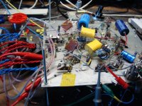
rcavictim said:Nothing wrong with making a breadboard,
From an accomplished expert..Everyone should go through this breadboard phase... does it sound as good as it looks ? this one does and it's stable. It's only a measly7W amp but a vastly improved Mullard orig. Performance spec will break glass.
richj
Attachments
richwalters said:rcavictim said:Nothing wrong with making a breadboard,
From an accomplished expert..Everyone should go through this breadboard phase... does it sound as good as it looks ? this one does and it's stable. It's only a measly7W amp but a vastly improved Mullard orig. Performance spec will break glass.
richj
Hmmmm (or probably lack thereof), a metal ground plane. That's cheating!
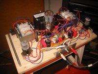
rcavictim said:Nothing wrong with making a breadboard, especially if it is developmental/transitional to a polished end product. Does it sound as good as it looks?
Can't say exactly how it sounds at the moment because it won't stay up long enough to form an opinion. I'm still tinkering/fighting with the ht, trying to teach it not to eat GZ34s.
Ed
rcavictim said:Nothing wrong with making a breadboard, especially if it is developmental/transitional to a polished end product. Does it sound as good as it looks?
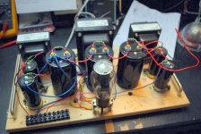
breadboard.... it looked like this.
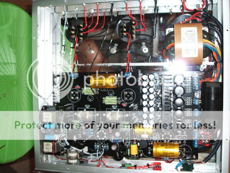
the main problem with the breadboard is space.
it just always gets BIG, mine looked like this:
and then like this...
same weight, same power, same sound.
Attachments
vitalstates said:
Can't say exactly how it sounds at the moment because it won't stay up long enough to form an opinion. I'm still tinkering/fighting with the ht, trying to teach it not to eat GZ34s.
Ed
Go with a pair of octal base TV damper diode tubes. Slow delayed warmup and gobs of voltage/current capability. GZ34 is for 'normal' amplifiers using 'normal' output tubes, not transmitter tube amps like SV572 or 811A.
vitalstates said:cheers bob,
I have been looking for 6d22s over here for some time but they are all in hiding at the moment. Thats why I had to compromise and go for GZ34.....what other easy to get & cheap dampers do you know of?
Ed
The two most common single diode dampers I am aware of are 6AX4 (165mA cont.). The higher current version is a 6AU4 (210 mA cont.). They both will handle the voltage you need but the filament winding should be separate from your other valves and transformer winding insulation on it good fo the B+ value to ground. It would be safe to parallel these if necessary to increase the supply current. Equalizing resistors should be unnecessary.

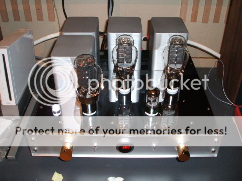
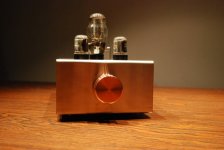
planet10 said:Very tidy... what iron did you use?
dave
Copperplate with electro nickel.
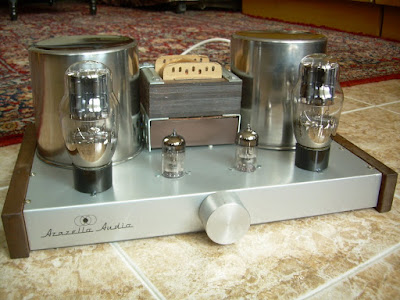
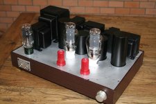
Here's my latest:
It's a DRD ultrapath design based on Jack Elliano's 300B DRD amp.
It uses TJ meshplate PX25s driven by GE 7044s or Tung Sol 5687s as the fancy takes me.
Steve
It's a DRD ultrapath design based on Jack Elliano's 300B DRD amp.
An externally hosted image should be here but it was not working when we last tested it.
It uses TJ meshplate PX25s driven by GE 7044s or Tung Sol 5687s as the fancy takes me.
Steve
Steve Cresswell said:Here's my latest:
It's a DRD ultrapath design based on Jack Elliano's 300B DRD amp.
An externally hosted image should be here but it was not working when we last tested it.
It uses TJ meshplate PX25s driven by GE 7044s or Tung Sol 5687s as the fancy takes me.
Steve
Nice layout. I like the fact that you made an effort to keep the rectifier valve isolated from the signal valves. I cringe when I see the capacitive coupling of the high voltage on the rectifier plates to the anodes of the signal valves on too many designs, especially commercial offerings where there is no excuse. A MingDa preamp springs to mind. Big honking 5U4 nested amongst small signal tubes. What were they thinking?
Thanks Bob
A lot of thought went into the layout. Virtually all of the right half of the amp is power supply.
After the placing of the rectifier as far from the small signal valves as I could get it, the big oil-filled PSU and Ultrapath caps were the biggest dictators of the layout.
The 4V PX25s are heated by DIYHiFiSupply DC heater modules. The amp is virtually silent in operation and I'm very pleased with its performance.
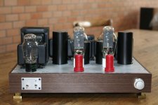
Here's the amp in situ with the rest of the system. Speakers are home built open baffles based on Fostex, Goodmans and Eminence units. Since the amplifier pic was taken I have gone SS with the rectification, which has been placed at the rear right hand corner of the amp and is now as far from the small signal circuitry as it is possible to get.
Steve
A lot of thought went into the layout. Virtually all of the right half of the amp is power supply.
After the placing of the rectifier as far from the small signal valves as I could get it, the big oil-filled PSU and Ultrapath caps were the biggest dictators of the layout.
The 4V PX25s are heated by DIYHiFiSupply DC heater modules. The amp is virtually silent in operation and I'm very pleased with its performance.
An externally hosted image should be here but it was not working when we last tested it.
Here's the amp in situ with the rest of the system. Speakers are home built open baffles based on Fostex, Goodmans and Eminence units. Since the amplifier pic was taken I have gone SS with the rectification, which has been placed at the rear right hand corner of the amp and is now as far from the small signal circuitry as it is possible to get.
Steve
- Home
- Amplifiers
- Tubes / Valves
- Photo Gallery