I was asked in an email how close the Phonoclone circuit is to the original. It's something that's come up before, a long time ago, but since I've never been quite satisfied with the answer I gave I will take another stab at it:
The Phonoclone is based on what is publicly known about the Phono Cube, plus some information divulged in private communication, and there was, at one point, a web page with details from someone who claimed to have taken it apart.
The basic topology is almost certainly correct, and the op amps OP27, are also very likely correct. Obviously I have no idea about the resistance and capacitance values used, but educated guesses, inter-relationships, and proper practice gets you most of the way there.
The phonoclone circuit as I have it has 13 parts per channel. R1 and, possibly, R4 can be left off and the circuit still function as per the known specifications, everything else is required. There isn't much else that can be added, but perhaps there is a capacitor across R2 for stability. So the range of parts is 11-14 per channel.
Now the Phono Cube has 25 parts per channel, the difference is surely the voltage regulation circuitry, which is duplicated for the two channels, and of course symmetric positive and negative. So the voltage regulation components must be an even number. That means the phonoclone circuit must be odd, either 11 (for 7 parts per voltage rail) or 13 (for 6 parts for voltage rail).
Now we come to the part that bothers me: What is the most likely voltage regulation components used? I has assumed LM317/337 with the bypass cap. With filter caps in and out, bypass cap, and the voltage divider, that's 6 components per voltage rail. Done.
It somehow seems out of character for Mr. Kimura to use these voltage regulators however. In keeping with his "simple is best" design philosophy, LM7815 LM7915 seem more likely, but it hard to come up with a reasonable configuration using fixed voltage regulators that uses 6-7 parts, typically only 3 are needed per voltage rail: the chip and two capacitors. At one point I entertained the idea of a RC filter on the regulator output, one for each op-amp. That ends up at 7 components but seems awkward and unnecessary.
Fast forward to today, and now I'm wondering if the zener-referenced pass transistor regulator was used. The circuit is used in my Sapphire amplifier. 3 caps, 1 transistor, 1 Zener, 2 resistors. 7 parts. Some times it's used without the second resistor.
It's quite possible. The reason I say that is it's unlikely the circuit with regular voltage regulators, be it LM317 or LM7815, would have sound as distinctive / good as the Phono Cube apparently does.
It's water under the bridge now anyway as I have replaced the whole voltage regulation with the custom X-reg circuit in the Phonoclone3, but I do think the simple Zener regulation circuit deserved a second look.
Phonoclone 35d
Several changed for version 35d
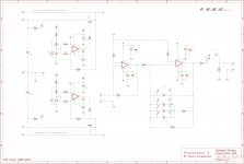
1. Redrew the circuit schematic to A3 frame size, it is a lot clearer now.
2. Added optional 0.1uF ceramic caps next to op amps IC1, IC2. This should provide stability when using high bandwidth op amps like OPA37.
3. Added wirepads for the regulated voltage rails V+ and V-. This means eiether A. you can access the X-reg output voltage to use to power a external buffer circuit for example, or B. you can omit the X-reg components and power the board from your own regulated or battery supply.
4. Put back the missing part label "C3"
5. Added a second pad for C3 to make it a little easier connecting larger axial coupling capacitors.
6. Minor edits to the trace layout.
7. Renamed the regulated voltage rails from V+reg, V-reg to V+ and V-, and renamed the filtered rails of the X-reg circuit from V+, V- to UB+, UB-. Unfortunately I used V+ to mean different things in the Xreg and phonoclone web pages, I prefer to be consistent with the usage of the phonoclone description, that is, V+ and V- are the regulated, internal voltage rails to the op amps while V++ and V-- are the unregulated, external supply connections.
Several changed for version 35d
1. Redrew the circuit schematic to A3 frame size, it is a lot clearer now.
2. Added optional 0.1uF ceramic caps next to op amps IC1, IC2. This should provide stability when using high bandwidth op amps like OPA37.
3. Added wirepads for the regulated voltage rails V+ and V-. This means eiether A. you can access the X-reg output voltage to use to power a external buffer circuit for example, or B. you can omit the X-reg components and power the board from your own regulated or battery supply.
4. Put back the missing part label "C3"
5. Added a second pad for C3 to make it a little easier connecting larger axial coupling capacitors.
6. Minor edits to the trace layout.
7. Renamed the regulated voltage rails from V+reg, V-reg to V+ and V-, and renamed the filtered rails of the X-reg circuit from V+, V- to UB+, UB-. Unfortunately I used V+ to mean different things in the Xreg and phonoclone web pages, I prefer to be consistent with the usage of the phonoclone description, that is, V+ and V- are the regulated, internal voltage rails to the op amps while V++ and V-- are the unregulated, external supply connections.
Attachments
Last edited:
Yes, the kit instructions and (eventually) the BOM will be updated to 35f once the new boards start shipping later this month. The web page and downloadable images and Eagle files have already been updated.
Note that the basic circuit values, kit contents and BOM do not change. The new boards just have space for an optional bypass capacitor which is not normally used or required... I will just make a note of that in the updated BOM.
Note that the basic circuit values, kit contents and BOM do not change. The new boards just have space for an optional bypass capacitor which is not normally used or required... I will just make a note of that in the updated BOM.
Attachments
Last edited:
................
It somehow seems out of character for Mr. Kimura to use these voltage regulators however. In keeping with his "simple is best" design philosophy, LM7815 LM7915 seem more likely, but it hard to come up with a reasonable configuration using fixed voltage regulators that uses 6-7 parts, typically only 3 are needed per voltage rail: the chip and two capacitors. At one point I entertained the idea of a RC filter on the regulator output, one for each op-amp. That ends up at 7 components but seems awkward and unnecessary.
................
Richard,
This what I did find a few weeks ago on the www, I can't remember the exact site but if you Google on a part of the text I am sure you will find the site. Edit...Did a search and found it again http://www.high-endaudio.com/RC-PhonoStages.html Scroll down till you find battery supply for PhonoCube.
For your information, I rebuilt my PhonoCube from top to bottom, upgrading the carbon resistors to nuded Vishay S102s, replacing the cheap coupling caps by BlackGate N Series, replacing the WIMA 20% MKP caps on the feedback circuits with high-grade mica and styroflex capacitors. The PCB was redesigned and the noisy LM78xx regulators were replaced by low noise precision regulators with discrete noise filtering. The cheap RCA jacks were replaced by Vampire CM1F/OFC on the output. The RCA jack on the input was removed and the wire from the cartridge was directly soldered to the input pins of the OP27G that forms the first gain stage of the PhonoCube.
I think that the writer means decoupling caps where he writes coupling caps cause the 47Labs Phonocube does not have coupling caps if Peter Daniel is right. Peter Daniel claims that his 'The Phono Stage' as far as for the phono part schematic is an exact copy of the Phonocube, he uses different parts as the original ('The Phono Stage' can be found on this site, on the first page you will find a schematic of the phono part). At the site of 47Labs you can read that the Phonocube 75dB version does not have enough gain for a Denon DL-103 (due to the relative high internal resistance of 40 ohm), your PhonoClone does have enough gain for a Denon DL-103.
With the writing above I do not mean to say that your PhonoClone is bad or better, it is just your implementation of a two OP AMP MC preamp wich is doing very well.
Ronald K.
Edit.
Forget to write about the PSU's, The 47 Labs Humpy/Dumpy PSU's have a (most likely) R-Core transformer with two secondaries with each a single rectifier (no caps in the PSU unit). Each PSU has two 4-pole connectors. The Phonocube does have 2 leads with each a 4-pole connector, one for each channel. Output voltage of the PSU is 24 Volt. I can imagine that before the 7815/7915 there will be one or more R/C networks to lower the voltage because otherwise the dissipation of the 7815/7915 will be quite high.
I do not think the PhonoCube will use 7818/7918 or 7812/7912 regulator...but you never know. (I love this kind of detective work, sorry)
Last edited:

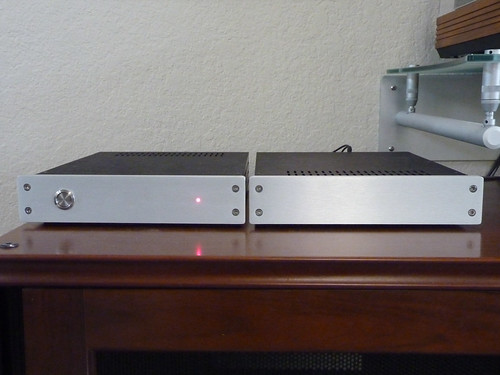
My first attempt at Electronics for years has produced this. Thanks to Richard for all his help.
Very nice cabinet, where did you buy it?
Ronald.
Very nice cabinet, where did you buy it?
Ronald.
Its a Galaxy with 10mm front from modushop.biz
I agree, its a lovely looking case.
Edit...Did a search and found it again REFERENCE COMPONENTS-PHONO STAGES
Ah, you found it! Wow. That's one of the sources I used when I was building the first phonoclone circuit. Careful with that webpage - it's an historical artifact!")
Completed Build (Almost)
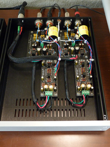
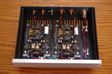
Final verison completed. Differenced from the stock PJM unit and build details are:
1) Power supply boards (CRCRC + Q-Speed diodes)
2) Tantalum resisitors in input section and RIAA filter
3) Audiocap Theta coupling cap + nuded Russion teflon bypass
4) Silver teflon signal wiring
5) Opamps directly soldered
6) Used Nichicon Muse caps for the IC supply bypassing
7) Used RJM's new buffer boards, inserted between the last IC output and the final coupling caps.
8) Measured and matched RIAA caps
After much meddling with AD797's I ended up keeping the OPA27 opamps in all positions. Cases are Modushop Galaxy.
P1050528.jpg by MartinC7, on Flickr

P1050526.jpg by MartinC7, on Flickr
P1050530.jpg by MartinC7, on Flickr
Still burning in (only been running for 30 mins) but very sweet. With the volume full there is slighly less noise than the stock build, I am guessing that this may be due to the tantalum resistors.
Anyway back to listening then some final wiring clean up.
Cheers
Final verison completed. Differenced from the stock PJM unit and build details are:
1) Power supply boards (CRCRC + Q-Speed diodes)
2) Tantalum resisitors in input section and RIAA filter
3) Audiocap Theta coupling cap + nuded Russion teflon bypass
4) Silver teflon signal wiring
5) Opamps directly soldered
6) Used Nichicon Muse caps for the IC supply bypassing
7) Used RJM's new buffer boards, inserted between the last IC output and the final coupling caps.
8) Measured and matched RIAA caps
After much meddling with AD797's I ended up keeping the OPA27 opamps in all positions. Cases are Modushop Galaxy.
P1050528.jpg by MartinC7, on Flickr
P1050526.jpg by MartinC7, on Flickr
P1050530.jpg by MartinC7, on Flickr
Still burning in (only been running for 30 mins) but very sweet. With the volume full there is slighly less noise than the stock build, I am guessing that this may be due to the tantalum resistors.
Anyway back to listening then some final wiring clean up.
Cheers
My first attempt at Electronics for years has produced this. Thanks to Richard for all his help.
The case for the PS and screen braid for the power lead have finally arrived, and I have managed to get it all hooked up and working correctly. Nice chunky 120va transformer with 8 Schottky Diode's in 2 bridges, case is from eBay The PhonoClone is in a Galaxy 10mm
Sounds rather good
Shed loads better than my Dynavector P75 it replaced. Bass appears less deep, but its just an illusion as its cleaner and more precise, as it the whole or the spectrum. There's more detail, more 'space' between instruments, everything is better.Overall its more precise, but not in an overly analytical way.
Yes, its staying.
Attachments
Last edited:
A somewhat strange observation, that has to be linked to the PC3.
Using the Dynavector P75 and all previous phono stages, when playing music at 'realistic' (ie window shaking) levels my Power Amp got quite hot. Now I can play music even louder without distortion and the Power Amp barely gets warm.
Nothing else in the system has been changed.
Using the Dynavector P75 and all previous phono stages, when playing music at 'realistic' (ie window shaking) levels my Power Amp got quite hot. Now I can play music even louder without distortion and the Power Amp barely gets warm.
Nothing else in the system has been changed.
Good point. I do suffer from RFI problems here. I have put a few turns of the arm lead through a ferrite ring to stop radio pickup on previous phono stages (its still there as I haven't been bothered to see if I still need it on not) and I still get 'thermostat switching' noises through the system.
I have managed to diminish it somewhat by putting caps across the PC3 input and output. I have yet to try one across the power pins of IC1 as Richard has suggested.
I have managed to diminish it somewhat by putting caps across the PC3 input and output. I have yet to try one across the power pins of IC1 as Richard has suggested.
- Status
- This old topic is closed. If you want to reopen this topic, contact a moderator using the "Report Post" button.
- Home
- Source & Line
- Analogue Source
- Phonoclone 3