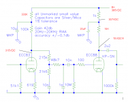
Looks like a place to start to me. One thing though: the 27k resistor
on the input tube cathode is obviously wrong. I'm guessing it should
be 2k7, or 2.7k ohms. Otherwise, fine. Keep cables short, including
interconnects. (There are no doubt more advanced preamps, but it
is not such a bad idea to start with a simple design.)
Morgan
on the input tube cathode is obviously wrong. I'm guessing it should
be 2k7, or 2.7k ohms. Otherwise, fine. Keep cables short, including
interconnects. (There are no doubt more advanced preamps, but it
is not such a bad idea to start with a simple design.)
Morgan
Morgan is correct - that resistor should be 2.7 K.ohm, or even 2.2 K.ohm (manuals give an optimum of 1.5 K.ohm, but it is not critical - valves have a spread anyway). I have quickly checked the response on a program and it appears to be in order for RIAA. You will have a nett gain of about 230.
The coupling capacitors (0.1 uF and the last one which I have not noted down) should be 400V. The 3.3 nF and 10 nF can be low voltage, typically the small 100V types. But the two cathode capacitors could also be low; 16 - 25V.
Just a small point; I do not know how experienced you are with valve amp construction. Remember to earth the metal (screening) tube in the middle of the sockets. Some folks miss this and it can lead to inadvertent capacitive coupling between electrodes and high frequency oscillation if not done.
Have fun!
That's QUITE close to the circuit found in RCA receiving tube manuals. It has the same strengths and weaknesses. The biggest weakness is absolutely wretched drive capability. As shown, that phono section has to be built on the same chassis as the line section and a 500 KOhm volume control is in order.
Here's a link to a thread Planet10 (DIY moderator) and I were involved in fairly recently that discussed the RCA circuit at some length.
RCA Phono Section
Here's a link to a thread Planet10 (DIY moderator) and I were involved in fairly recently that discussed the RCA circuit at some length.
RCA Phono Section
Eli - Yaai!
I did want to add about the high output impedance and forgot dismally - thanks for pointing that out. (Perhaps I should not be up this time of night.) Also, the cathode bypasses are too low. Somehow I registered 470uF and analysed with that. The RCA circuit's 25uF is definitely too low, and so will be 47uF. Capacitors are small and inexpensive these days, and I would suggest 470uF. Some folks make heavy whether of using electrolytics here; in my opinion that is a bit overdone - this is an entry-level circuit. If PB wants he could use the grid-leak method of bias which works for an ECC83 for low level signals. That entails another 2 R-Cs, but they replace the cathode bias R-Cs.
Now I will go to bed before I overlook more things.
Konnichiwa,
Actually, with 47uF as in the circuit discussed you get in the second stage a dominant pole at 5Hz and in the first stage at 2.5Hz (close estimate) which with the permissable 500K load on the output (as given as for the RCA circuit it resembles) and the RIAA Network & coupling network having each around 1.5Hz turnover means the 10hz pole from the second stage becomes dominant.
In other words, as is, the -3db point of the phonostage will be well below 10Hz. So, the 47uF used by the circuit are EMPHATICALLY NOT TOO LOW in value.
Also, my ECC83/ECC88 Phonocircuit was designed mainly to overcome ALL the problems in the RCA circuit.
Sayonara
Johan Potgieter said:the cathode bypasses are too low. Somehow I registered 470uF and analysed with that. The RCA circuit's 25uF is definitely too low, and so will be 47uF.
Actually, with 47uF as in the circuit discussed you get in the second stage a dominant pole at 5Hz and in the first stage at 2.5Hz (close estimate) which with the permissable 500K load on the output (as given as for the RCA circuit it resembles) and the RIAA Network & coupling network having each around 1.5Hz turnover means the 10hz pole from the second stage becomes dominant.
In other words, as is, the -3db point of the phonostage will be well below 10Hz. So, the 47uF used by the circuit are EMPHATICALLY NOT TOO LOW in value.
Also, my ECC83/ECC88 Phonocircuit was designed mainly to overcome ALL the problems in the RCA circuit.
Sayonara
Konnichiwa,
Nope, mine is a bit less compromised.
It was originally intended for a commercial product that ended up never build and was hence released into the public domain here:
http://www.diyaudio.com/forums/showthread.php?postid=335624#post335624
This is my circuit:
As you can see, unlike some others I am morbidly concerend to keep the signal circuit completely free of electrolytic capacitors (no Black Gates allowed either) simply because I actually tested them blind against a wire bypass and feel them to be completely unacceptable.
Key changes compared to the RCA Circuit are:
1) Converted second stage to ECC88/6DJ8/6922 to reduce output impedance, the Circuit is fine to drive a 10K load (tested)
2) Used gridleak bias on the second stage and removed the cathode bypass capacitor in the first stage, re-arranged first stage for low anode voltage operation which usually gives much lower noise
3) Changed the the RIAA circuit to whta I call "Kondo" or "semi-split" circuit, this has the advantage to allow for completely seperate adjustment of the capacitors in the circuit
4) Moved the coupling capacitor behind the RIAA so the RIAA capacitors dielectric is "soaked" (avoiding any issues from "soakage" [which is also known as "dielectric absorbtion"] on the signal) and the interaction between coupling cap & first RIAA cap (and thus on the RIAA EQ)
Sayonara
philipbarrett said:Kuei is this your circuit?
Nope, mine is a bit less compromised.
It was originally intended for a commercial product that ended up never build and was hence released into the public domain here:
http://www.diyaudio.com/forums/showthread.php?postid=335624#post335624
This is my circuit:
An externally hosted image should be here but it was not working when we last tested it.
As you can see, unlike some others I am morbidly concerend to keep the signal circuit completely free of electrolytic capacitors (no Black Gates allowed either) simply because I actually tested them blind against a wire bypass and feel them to be completely unacceptable.
Key changes compared to the RCA Circuit are:
1) Converted second stage to ECC88/6DJ8/6922 to reduce output impedance, the Circuit is fine to drive a 10K load (tested)
2) Used gridleak bias on the second stage and removed the cathode bypass capacitor in the first stage, re-arranged first stage for low anode voltage operation which usually gives much lower noise
3) Changed the the RIAA circuit to whta I call "Kondo" or "semi-split" circuit, this has the advantage to allow for completely seperate adjustment of the capacitors in the circuit
4) Moved the coupling capacitor behind the RIAA so the RIAA capacitors dielectric is "soaked" (avoiding any issues from "soakage" [which is also known as "dielectric absorbtion"] on the signal) and the interaction between coupling cap & first RIAA cap (and thus on the RIAA EQ)
Sayonara
Konnichiwa,
If you want to use a 350V supply "Just Do It".
Increase the anode decoupling resistor in the first stage to 330K from 180K and increase the anode load resistor of the output stage from 12K to 15K or even 18K. This will give slightly more gain and linearity from the output stage and put those extra 100V to good use. All else remains the same.
BTW, note the circuit needs a good deal of current, around 25 - 30mA for both channels!
Sayonara
philipbarrett said:Your corcuit was actually my 1st choice, I really liked the elegence & simplicity. I have already built a 350V PSU so was looking to leverage that into a design, hence the other choice. Maybe I should re-work the PSU?
If you want to use a 350V supply "Just Do It".
Increase the anode decoupling resistor in the first stage to 330K from 180K and increase the anode load resistor of the output stage from 12K to 15K or even 18K. This will give slightly more gain and linearity from the output stage and put those extra 100V to good use. All else remains the same.
BTW, note the circuit needs a good deal of current, around 25 - 30mA for both channels!
Sayonara
Kuei Yang Wang said:Konnichiwa,
If you want to use a 350V supply "Just Do It".
I'm on it - started today, I'll keep you updated. Thanks for everything.
__________________________
"I know you, you Nexus 6, I make your eyes."
Konnichiwa,
Consider reading again the various threads, especially Koffi Annan's "+B Plus" or something like that. Have a look around.
Sayonara
philipbarrett said:I'm on it - started today, I'll keep you updated. Thanks for everything.
Consider reading again the various threads, especially Koffi Annan's "+B Plus" or something like that. Have a look around.
Sayonara
Kuei Yang Wang
Yes, in your post #7 your frequencies are quite correct! That night (my post #6) was definitely not my best. My apology to the group. Think I must have used the 47uF after all and not 470uF as stated - can't retrace that now.
[Personal courtesy note to you, moderator allowing: I did not reply to your previous post to me regarding this matter in general in another thread (you would remember which one), because I experienced it as just a bit personal, and I do not reply to personal slants in technical discussions. You obviously know your subject, and your contributions are valuable. That I respect. Regards.]
Yes, in your post #7 your frequencies are quite correct! That night (my post #6) was definitely not my best. My apology to the group.
Think I must have used the 47uF after all and not 470uF as stated - can't retrace that now.[Personal courtesy note to you, moderator allowing: I did not reply to your previous post to me regarding this matter in general in another thread (you would remember which one), because I experienced it as just a bit personal, and I do not reply to personal slants in technical discussions. You obviously know your subject, and your contributions are valuable. That I respect. Regards.]
So the tubes arrived and I finally got the phono pre together using the latest schematic and notes you kindly gave to use with my 385V psu. I metered everthing before installing the tubes & all was OK, good voltages everywhere, fixed a couple of shorts to ground. I also tied the heater center taps to ground.
Once I installed the tubes things got more interesting; the 1st stage seems fine but the 2nd stage voltage readings at the plate are 75VDC (naturally the 15K resistor got roasting hot).
My only change from the published circuit & corrections was the use of two 20uF caps (I had some already) in place of the 2nd stage 22uF caps. Anyway, tell me what you think, revised circuit with voltage readings is below.
Thanks in advance for any help you can give.
PB
Attachments
Konnichiwa,
315V is WAY HIGH, it should be around 100V.
The voltage is fine, just what it should be, if your resistor gets hot I think you did not use one having sufficient dissipation (12W Wirewound recommended).
Sayonara
philipbarrett said:the 1st stage seems fine
315V is WAY HIGH, it should be around 100V.
philipbarrett said:but the 2nd stage voltage readings at the plate are 75VDC (naturally the 15K resistor got roasting hot).
The voltage is fine, just what it should be, if your resistor gets hot I think you did not use one having sufficient dissipation (12W Wirewound recommended).
Sayonara
Thanks - newbie problems found;
1) miscalculated the wattage (had a 2 watt, 15K in there)
2) read the color-code wrong & put a 300R on the ECC83, hence the voltage!
Questions;
1) what should the voltage read at the ECC83 plate?
2) what should the wattage be for the 1st stage plate resistors (once I get the values correct)?
As usual, you guys are great!
PB
Konnichiwa,
100ish Volts, not super critical.
1W will be plenty.
Sayonara
philipbarrett said:1) what should the voltage read at the ECC83 plate?
100ish Volts, not super critical.
philipbarrett said:2) what should the wattage be for the 1st stage plate resistors (once I get the values correct)?
1W will be plenty.
Sayonara
OK - had time to get back on this baby. Followed the ECC83 plate feed to the letter; 330K - 10uF - 100K but with a B+ of 320VDC I'm still reading 265VDC at the plate!
Also I am only measuring a gain factor of 2, put in 10mV/400Hz and saw about 20mV out on my scope. Good news is that it's real clean.
Hmmmmm?
Any ideas?
Thanks to the brain-trust in advance.
PB
Also I am only measuring a gain factor of 2, put in 10mV/400Hz and saw about 20mV out on my scope. Good news is that it's real clean.
Hmmmmm?
Any ideas?
Thanks to the brain-trust in advance.
PB
Konnichiwa,
Maybe the cathode resistor is wrong in value, you are only drwaing 120uA anode current....
Sayonara
philipbarrett said:OK - had time to get back on this baby. Followed the ECC83 plate feed to the letter; 330K - 10uF - 100K but with a B+ of 320VDC I'm still reading 265VDC at the plate!
Also I am only measuring a gain factor of 2, put in 10mV/400Hz and saw about 20mV out on my scope. Good news is that it's real clean.
Maybe the cathode resistor is wrong in value, you are only drwaing 120uA anode current....
Sayonara
- Status
- This old topic is closed. If you want to reopen this topic, contact a moderator using the "Report Post" button.
- Home
- Amplifiers
- Tubes / Valves
- Phono Pre-Design Input