Thank you Rayma! Hope you don’t mind I take a minute of your time but could you be so kind to explain me how did you come from the original circuit to this one while keeping the riaa equalization? (if it's not going to take you too much time of course).
One last question about the plate and cathode resistors on the cathode follower. Since the voltage coming into the grid is going to be b+ minus the drop across the 25k resistor and the two paralleled resistors (50k+39.4k) I think there is probably no need for a plate resistor. On the cathode resistor on the other hand I don't know how to proceed. It should not exceed the maximum difference of 150V between cathode and filament voltages but apart from that?
One last question about the plate and cathode resistors on the cathode follower. Since the voltage coming into the grid is going to be b+ minus the drop across the 25k resistor and the two paralleled resistors (50k+39.4k) I think there is probably no need for a plate resistor. On the cathode resistor on the other hand I don't know how to proceed. It should not exceed the maximum difference of 150V between cathode and filament voltages but apart from that?
The FVP5A needs the shunt regulator to operate properly. It needs the 50K pot on the output. Since all you would need to add is a couple of tubes and another heater supply, why not build the linestage section as well, so you know the phono is operating into an ideal load... I.E., just build the whole preamp... ")
Thank you Rayma! Hope you don’t mind I take a minute of your time but could you be so kind to explain me how did you come from the original circuit to this one while keeping the riaa equalization? (if it's not going to take you too much time of course).
One last question about the plate and cathode resistors on the cathode follower. Since the voltage coming into the grid is going to be b+ minus the drop across the 25k resistor and the two paralleled resistors (50k+39.4k) I think there is probably no need for a plate resistor. On the cathode resistor on the other hand I don't know how to proceed. It should not exceed the maximum difference of 150V between cathode and filament voltages but apart from that?
Sure, but first I am sorry, and was rushed and made a mistake. A 50k in parallel with the 32.4k is not the right resistance for the RIAA,
because of the 6922 stage's output impedance. The correct series resistor value must take that into account, when removing the 50k output loading.
The 50k load can be "transformed" into part of the series resistor by a principle known as Thevenin equivalence.
Thévenin's theorem - Wikipedia, the free encyclopedia
In this case, the series resistance is the 6922 stage's output impedance R0, PLUS the 32.4k, and the shunt resistance is the 50k volume control.
Once the 6922 stage's output resistance R0 is calculated, the correct value to replace the 32.4k before the cathode follower
is equal to: (50kx32.4k-R0^2-R0x32.4k) / (R0+32.4k+50k). This presumes that the original 32.4k resistor is the correct RIAA value.
The shunt RC network stays the same and does not affect the calculation in this case.
The cathode follower's cathode resistor could be in a certain range of values, but 25k would be fine and will reduce power supply modulation.
A plate resistor is not necessary here , and in fact would impair the operation. You can float the filament supply to say +50V if necessary.
Last edited:
Thank you!
Something like this if I have understood correctly.
This is incorrect. 1meg parallel 50 K is about 47.6K.
You need 47.6 k from grid to ground and no coupling cap. There is no resistor in parallel with 32.4K . This 47.6 K will come in parallel with 1.4K+3.3nF. DC voltages and currents will change. Maybe you shouldn't mess with this if you aren't expert enough.
As just suggested by 6L6 , maybe it's better the preamp is built as it is. Will lead to less errors and experimentation or maybe blue smoke !
Last edited:
This is incorrect. 1meg parallel 50 K is about 47.6K.
You need 47.6 k from grid to ground and no coupling cap. There is no resistor in parallel with 32.4K . This 47.6 K will come in parallel with 1.4K+3.3nF. DC voltages and currents will change. Maybe you shouldn't mess with this if you aren't expert enough.
Please read the post 23 above for more detail, it is correct, just using the 50k paralleled with 1M (47.6k) in the equation.
You can't add a 47.6k resistor to ground without a coupling capacitor before it, this would seriously disturb the DC operating conditions
of the tube, since the plate resistor is 25k. The above circuit avoids that problem, along with allowing him to use his present attenuator that
has a variable input impedance. This was his entire purpose.
Last edited:
.....DC voltages and currents will change. ....
As just suggested by 6L6 , maybe it's better the preamp is built as it is. Will lead to less errors and experimentation or maybe blue smoke !
I would really like to thank you all for taking your time helping me! I really appreciated it
I have calculated the output impedance of the last tube with this online calculator (Preamp Output Impedance Calculator) and the result was ~10k. Using the equation Rayma posted ((57.6k x 32.4k - 10k^2-10kx32.4k) / (10+32.4k+50k)) I obtained a value of ~12,4K (If my calculations were correct). Anyway since this is influencing the riaa curve probably the best thing to do is to check it once it's build and eventually trim the values to obtain the best possible response.
I know it would have been a simpler idea to build the whole preamp as it is but I have already builded the Kondo clone and I really like how it sounds. I wanted to build a phono pre that could be used whit the kondo line pre and that could work with mc cartridges without a step up transformer. This Allen Wright's project looked like the best one to me.
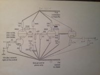
This is how at the end it should look like
I have calculated the output impedance of the last tube with this online calculator (Preamp Output Impedance Calculator) and the result was ~10k. Using the equation Rayma posted ((57.6k x 32.4k - 10k^2-10kx32.4k) / (10+32.4k+50k)) I obtained a value of ~12,4K (If my calculations were correct). Anyway since this is influencing the riaa curve probably the best thing to do is to check it once it's build and eventually trim the values to obtain the best possible response.
I know it would have been a simpler idea to build the whole preamp as it is but I have already builded the Kondo clone and I really like how it sounds. I wanted to build a phono pre that could be used whit the kondo line pre and that could work with mc cartridges without a step up transformer. This Allen Wright's project looked like the best one to me.
This is how at the end it should look like
Attachments
I would really like to thank you all for taking your time helping me! I really appreciated it
I have calculated the output impedance of the last tube with this online calculator (Preamp Output Impedance Calculator) and the result was ~10k. Using the equation Rayma posted ((57.6k x 32.4k - 10k^2-10kx32.4k) / (10+32.4k+50k)) I obtained a value of ~12,4K (If my calculations were correct).
Please use 47.6k instead of 50k, to include the small effects of the 1M resistor.
The series RIAA resistor is then = (47.6k x 32.4k-R0^2-R0x32.4k) / (R0+32.4k+47.6k)
= (47.6k x 32.4k - 10k^2 - 10k x 32.4k) / (10k + 32.4k + 47.6k) = 12.42k
Bear in mind that this circuit is quite sensitive to the tube's output impedance, so trimming of the 12k would be ok.
The impedance levels could be scaled up to reduce this problem. Both of the resistors could be multiplied by say 3.3,
and the C could be decreased by the same factor. The prior part of the RIAA (between the two stages) could remain the same,
since it is isolated form this part of the circuit. For example, if the C is chosen as 1nF, the series R would be 64k and the shunt R would be 4.62k.
Last edited:
I copied wrongly the formula but yes, I've used the 47,6k value in my calculations. Thank you anyway for pointing out the mistake!
Now I have "only" to build it and test it!
You can build an inverse RIAA network to use with your signal generator to check the response.
http://www.hagtech.com/pdf/riaa.pdf


I have now builded the modified version of the FVP5A with the cathode follower as posted above.
It works very well. It sounds beautifully, with an impressive sound stage and very clear tones.
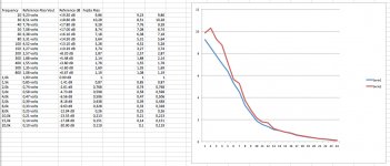
I'm just trying to trim the riaa curve as perfectly as possible. This is what I got up to now.
It works very well. It sounds beautifully, with an impressive sound stage and very clear tones.
I'm just trying to trim the riaa curve as perfectly as possible. This is what I got up to now.
Attachments
- Status
- This old topic is closed. If you want to reopen this topic, contact a moderator using the "Report Post" button.
- Home
- Source & Line
- Analogue Source
- phono FVP5A