Cone excursion is the math integral of cone speed. Try what Jean-Marc Plantefève is doing : 2A & DIYIs it possible to have a cone excursion output too?
Last edited:
Another way to look at this is to compare the Bode Plot having feedback in action, with the Bode Plot having feedback set to zero. Using an adjustable resistor or capacitor in LTspiceIV, like I have done on all supplied graphs. You then visualize the frequency domain where feedback actually is, where distorsion gets reduced.I've looked at the loop gain of the circut with the greatest gain set (RMFB=39K) and it peaks at only 4 at about 90Hz, dropping off rapidly either side. With 150K the loop gain peaks at 1! From a Control Systems point of view a loop gain of 4 is minute. For comparison opamps used as a buffer in audio gear boast great specs by having a loop gain of about 100 000 at 90Hz. The limited loop gain would reduce some harmonics (but its only really there over a small frequency band) but would also cause a dip in the fundamental. Perhaps this is made up by some boost in a previous filter.
Last edited:
Sorry for responding your kind post quite late. Actually, I may sell these after having converted "ordinary" speakers (like inexpensive DY-200 Dynavox drivers available on eBay - eine der größten deutschen Shopping-Websites) using a piezo disc and a buffer opamp, just like Elektor did long time ago. Why am I trying this ? Because I have noticed that the Philips MFB membranes suffer from very early very abrupt cone breakup. If you really need those, currently there are RH541, MFB drivers, FB9638 and MFB-like speakers along with a very interesting Uher "EG 740 + VG 840" mini HiFi on sale on eBay - eine der größten deutschen Shopping-Websites. Over there, search "philips aktiv" or "philips MFB".Hello, can you sell your 2 speaker PHILIPS AD 7066 MFB ? Sincerely. Jean-Pierre. SAINT-MALO. FRANCE.
Last edited:
Philips sensor used in all flat-membrane MFB woofers like the F9638 speaker system. See attached pictures. Is it a round-shaped PCB or is it a Piezo disc ? Are the required JFET and two resistors glued at the back ?
Here is the servicemanual for the F9638,
You can see they use a standard piezo disc with no electronics integrated in the woofer.
http://docs.mfbfreaks.com/sm/Service_Manual_F9638.pdf
Yes indeed. Elektor solution was better, with a DC-coupled low-noise FET opamp as unity gain buffer. And a 10 Meg or 22 Meg Ohm input resistance for a very low cutoff frequency.You can see they use a standard piezo disc with no electronics integrated in the woofer.
Attachments
This is Differential Pressure FeedBack (dPFB). Not Motional FeedBack (MFB). Looks interesting indeed. Need to simplify the whole design because at the moment it looks like a nuclear power plant.Modern version of motional feedback. Virtually the same thing, yet different enough for Powersoft to get a patent on it.
A very nice way to explore, from a diyAudio perspective.
Need to model the dPFB system using LTspice. Are you interested?
Need to select an inexpensive differential pressure sensor.
We have the Motorola (Freescale) MPX2100 series. 100 kPa range. 40mV full scale. What frequency bandwidth and phase behavior?
Need to select inexpensive zero-delay 16-bit ADCs and DACs operating at 384 kHz, hoping we can maintain some useful pressure feedback up to 340 Hz or so. Sound wavelenght at 340 Hz is 1 meter. The 384 kHz sampling frequency is needed for simplifying the analog antialias filters. Say we use Bessel lowpass 5th-order at 19.2 kHz or so. The Nyquist frequency (192 kHz) gets thus attenuated by more than 80 dB. Seems a valid starting point.
Need to base on Microchip PIC32MX2 (two SPI) or ARM Cortex-M0 (two SSP) for getting enough computing power (would be nice to rely on 32x32+64=64 arithmetic) and flexible serial ports for interfacing the ADC and DAC.
I'm very curious to see if dPFB can apply to dual-chamber 4th-order bandpass subwoofers and triple-chamber 8th-order bandpass subwoofers (aka Bose).
Attachments
Last edited:
The Ipal is quite cheap for the power and it comes with all the software you need. A module costs around $2000.
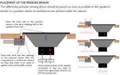
But obviously its probably more expensive than DIY. From my understanding the sensor needs to be placed near the cone, but in a location that does not get too much turbulence. With a bit of trial and error you could do it the way you proposed. It would make a nice DIY kit.
But obviously its probably more expensive than DIY. From my understanding the sensor needs to be placed near the cone, but in a location that does not get too much turbulence. With a bit of trial and error you could do it the way you proposed. It would make a nice DIY kit.
We can do it for less than $200, more powerful, more flexible, all-in-one (no PC required for the setup).
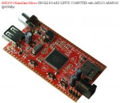
If only one SSP (bidirectional) is needed for interfacing the ADC and DAC, a nice hardware platform is OLIMEX iMX233 OlinuXino. SSP1 is hardwired to the Compact Flash. SSP2 should remain available for the audio ADC and DAC.
See it here https://www.olimex.com/dev/imx233-olinuxino-micro.html
There is a composite video out. The board can thus connect to a monitor and a mouse (or trackpad) for setting up the parameters. No PC would be required.
Software upgrades would remain possible thanks to USB.
Attachments
")
A recurrent question about MFB systems, is to know the details of the acceleration sensor. I think I'm able to provide some answer now.
Using LTspice, I managed to simulate the PHILIPS RH544 Motional Feedback loudspeaker. This forced me to simulate the acceleration sensor.
In the attached .zip file, you will find a couple of LTspice simulations.
You need to unzip the .zip file into a proper directory on your computer.
Then, by clicking on a .asc file, you can run the simulation. Of course you need LTspice to be installed on your computer.
The first .asc simulation to be run is the "Philips RH544 MFB 16dB (ac)".
Over there you can see how I simulated the acceleration sensor, and the electrical interface. Please note the phase inversion embedded into E1. This was required for the feedback, to act as negative feedback. As you can see, the feedback is 16 dB at 90 Hz, and the frequency response curve looks very nice.
Basing on such knowledge, I derived a few homemade MFB simulations, so anybody can easily play with MFB.
"Closed Box MFB Philips 12 dB design" step 1 to step 4 show how to design a high quality MFB system maintaining the MFB effect even in the very low frequencies. The price to be paid for such high quality, is the addition of a pre-equalizer.
The MFB equals 12 dB at 90 Hz.
The MFB equals 6 dB at 50 Hz. One can thus expect a 50% distortion reduction at 50 Hz.
The MFB equals 2.5 dB at 32 Hz. One can thus expect some distortion reduction at 32 Hz.
"Closed Box MFB Philips Leaking Integrator 12 dB" step 1 to 2 show how to design a simpler however tricky MFB system, that's no more requiring a pre-equalizer. The integrator that's following the piezo sensor preamp is tweaked, by a carefully chosen "leakage resistor" that's actually reducing the MFB below a certain frequency. This actually boosts the speaker output below a certain frequency, obviating the need for a pre-equalizer.
The MFB equals 12 dB at 90 Hz.
The MFB equals 5 dB at 50 Hz. One can thus expect an almost 50% distortion reduction at 50 Hz.
The MFB equals 0 dB at 32 Hz. The MFB stops thus here. There won't be any distortion reduction at 32 Hz, and below.
Depending on the piezo sensor behavior at high frequency, one can possibly apply more than 12 dB MFB.
"Closed Box MFB Philips Leaking Integrator 15 dB" step 1 to 2 show how to setup a 15 dB MFB.
The most important job is to determine the two compensating networks that are required for attaining an overall flat frequency response, once the MFB gets in use.
One compensating network goes into the action chain (power amplifier).
The other other compensating network goes in the feedback chain (the MFB). This way, even when reformatting the resulting frequency response, the stability doesn't get impacted. This is because the two compensating networks balance themselves t(they are symmetric), when put in series inside the servo loop.
Then, playing either with the "leaking integrator", or the "pre-equalizer" one can extend and flatten the very deep bass end of the frequency response curve.
Please note, the above homemade MFB simulations cannot be made in thez real world, using the Philips sensor (the Philips MFB speaker drivers). For this to become possible, one should phase-reverse the electrical signal coming from the Philips piezo sensor.
In case you base on a vintage Philips speaker driver having the MFB sensor (and preamp) inside, you need to wire an additional opamp inside the servo-loop, as inverting 0 dB amplifier (inverter).
In case you base on a normal speaker driver, in which you mount a piezo disc as acceleration sensor, you can orient the disc the way you want. This way the piezo disc will send an electric signal, having the required phase.
Attachments
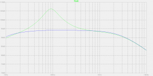
Attached are the frequency response curves of the two different approaches.
From 10 Hz to 30 Hz, the Leaking Integrator (no pre-equalizer) approach exhibits a 2nd-order highpass.
From 10 Hz to 30 Hz, the pre-equalizer approach exhibits a 1st-order highpass.
The pre-equalizer approach will thus exhibit the best transient response.
From 10 Hz to 30 Hz, the Leaking Integrator (no pre-equalizer) approach exhibits a 2nd-order highpass.
From 10 Hz to 30 Hz, the pre-equalizer approach exhibits a 1st-order highpass.
The pre-equalizer approach will thus exhibit the best transient response.
Attachments
Last edited:
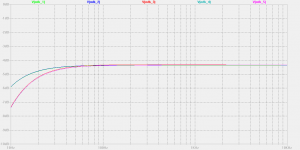
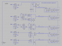
Attached is a comparison showing various piezo accelerometer interfaces.
The MFB_1 is the Philips interface that you can find in the Philips RH541, RH544, RH545, RH567, etc. MFB loudspeakers. The piezo sensor load is a 20 meg ohm resistor for preserving the low frequencies. The JFET converts the piezo voltage into a variable current. This enables a low impedance link, quite immune to hum and other electromagnetic pollution. A slight drawback is C101 required as AC coupling.
The MFB_2 interface benefits from the INA134 90 dB common mode rejection. Unfortunately, the INA134 exhibits a 50 kilo ohm differential impedance, instead of the 20 meg ohm differential impedance that's required for preserving the low frequencies. Two external buffers provide the required high input impedance. Such balanced structure permits the use of a high impedance balanced link, highly susceptible to hum and other electromagnetic pollution, that the INA124 is supposed to cancel.
The MFB_3 interface also benefits from the INA134 90 dB common mode rejection. Unfortunately, the INA134 exhibits a 50 kilo ohm differential impedance, instead of the 20 meg ohm differential impedance that's required for preserving the low frequencies. For restoring the low frequencies, X301 is wired as equalizer thanks to C301 (20 nF) and R306 (5 kilo ohm). R305 (1 meg ohm) is there for avoiding X301 to deliver an infinite amplification for the DC. The C301 R305 combination determines a highpass behavior, attenuating the MFB signal below 8 Hz.
The MFB_4 interface bases on a low input impedance amplifier enabling a low impedance link, quite immune to hum and other electromagnetic pollution. A slight drawback is the 20 dB voltage attenuation showing at the output of X400, because of using C400 (20 nF) that's bigger than the piezo capacitance (assumed to be 2 nF). A value of 20 nF was chosen for C400, knowing it is required to limit the DC gain of X400 using a high value resistor (R402), that should not exceed 1 meg ohm for keeping noise below a decent threshold. The C400 R402 combination determines a highpass behavior, attenuating the MFB signal below 8 Hz.
Please note the 20 dB gain increase that's required in the integrator that's following. This may cause noise.
The MFB_5 interface relies on a single-ended buffer for loading the piezo sensor with a 10 meg ohm resistor for preserving the low frequencies. The link is high impedance, highly susceptible to hum and other electromagnetic pollution. As the link is not balanced, there is no pollution cancellation effect. The MFB signal will contain some hum and other electromagnetic pollution, to some degree. It may be acceptable, in case the link provides some shielding. One can try using a stereo headphone cable as link. There are 2 x 2 conductors, quite flexible, to be considered as 2 x (shield & signal).
Attachments
Last edited:
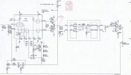
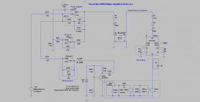
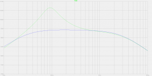
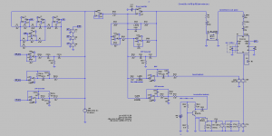
Attached is a simplified, intuitive way to organize the Motional Feedback.
Let's define a particular frequency F1 in the order of 200 Hz :
a) above F1, the voltage feedback must become dominant
b) below F1, the Motional Feedback (acceleration signal) must become dominant
The first condition is satisfied by putting a capacitor in series (C100) with the voltage feedback resistor (R100) of the power amp (X100).
This has as adverse effect, that the DC amplification of the power amp becomes infinite.
We therefore add a high value resistor (R102) in parallel with C100. The DC amplification is no more infinite, albeit very high (R102 divided by R101 roughly).
And, for avoiding a huge DC offset showing at the output of the power amp, we introduce a DC-servo arrangement forcing the power amp output voltage to equal zero for the DC and all subsonic frequencies below 20 Hz or so.
This way, there is still a frequency band where there is almost no feedback. Such frequency band starts from 20 Hz or so (top end of the subsonic frequency band) to F1 (frequency where the power amplifier voltage feedback becomes dominant).
Having done this, we need to organize the MFB circuitry in such a way that the MFB is in control below F1, and gradually ceases above F1.
At the collector of Q400, we get the acceleration signal that's reflecting the SPL delivered by the speaker (SPL is acceleration).
We know there are two parasitic highpass filters in the MFB chain :
a) the capacitve nature of the piezo transducer (say 2 nF) that's loaded by some high value resistance (say 20 meg ohm at the best), determining a 4 Hz highpass,
b) the coupling capacitor (10 µF) in Q400 collector, that's loaded by 38.8 kilo ohm (R401 + R_MFB), determining a 0.4 Hz highpass.
Because of the two highpass filters, we fear the MFB to cease control below 4 Hz, causing a dramatic SPL increase below 4 Hz. This won't actually happen as below 20 Hz or so, the system gets controlled by the DC-servo.
So, finally, for the MFB to take control below F1, and gradually cease above F1, we simply need to filter the MFB signal using a lowpass filter attenuating above the F1 frequency. This is done by R300 and C300.
In the example shown, R300 equals R100, and C300 equals C100. This way one can see the direct analogy that's existing between the power amplifier voltage feedback, and the cone acceleration feedback.
Such simple and intuitive way of organizing the MFB produces decent results. I strongly advise everybody to start with this.
Attachments
-
Closed Box MFB Philips simplified 590 Hz (ac).asc8.6 KB · Views: 86
-
Closed Box MFB Philips simplified 268 Hz (ac).asc8.6 KB · Views: 57
-
Closed Box MFB Philips simplified 125 Hz (ac).asc8.6 KB · Views: 70
-
 Closed Box MFB Philips simplified 268 Hz (schema).png60.3 KB · Views: 205
 -
 Closed Box MFB Philips simplified 268 Hz (curves).png23.3 KB · Views: 221
Last edited:
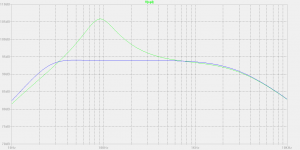
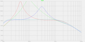
Attached are simulations aiming at combining Acceleration Feedback with Speed Feedback.
The acceleration signal is supposed to come from a piezo sensor.
It gets lowpass filtered at 100 Hz. Such signal serves thus as main feedback below 100 Hz.
Due to the fact that the piezo element is of capactive nature (say 2 nF) loaded by a resistor (say 20 meg ohm), the acceleration feedback progressively ceases below 4 Hz. There is thus no acceleration feedback at subsonic frequencies and below. The frequency response curve will be problematic below 4 Hz, exhibiting some unwanted amplification, possibly ruining stability.
The speed (velocity) signal is supposed to come from a Voight bridge.
It gets bandpass filtered. Such signal serves as main feedback between 150 Hz and 600 Hz.
A time derivator (+6 dB slope) is required for transforming it into an acceleration, prior injecting it into the system.
Above 1000 Hz, the power amplifier gets its negative feedback from its own output, through a highpass passive filter. This ensures stability above 1000 Hz.
A DC-servo loop is required for avoiding some unnecessary amplification in the subsonic frequencies. The stability of the DC-servo loop is tricky. It requires a parallel RC network acting as subsonic frequency compensation in the power amplifier feedback network (2.2 meg ohm / 15 nF).
Using such machinery, the motional feedback can be greater than 10 dB from 50 Hz to 220 Hz.
This is the ideal case. The actual performance is function of the Voight bridge precision. As soon as the Voight bridge gets out of balance (temperature effect on the copper coil, production spread, components tolerance and aging), the Speed (velocity) Feedback signal gets corrupt.
In such implementation, the two acoustic feedback loops are necessary. As soon as one of the two acoustic feedback loop goes away, the frequency response curve becomes catastrophic, possibly unstable, possibly destructing the power amplifier and/or speaker.
Debugging such circuit is thus complicated.
Definitely not recommended for newbies.
Attachments
- Status
- This old topic is closed. If you want to reopen this topic, contact a moderator using the "Report Post" button.
- Home
- Loudspeakers
- Multi-Way
- Philips Motional Feedback (MFB)