Hi all
rwtomkins, I'll second you there
I have a PCMII and a PCM7000, and would love to get the inside info on the PCMII. The bonnet's going up on the PCM7000 soon as the right channel occasionally doesn't show up for work . Both units are stock standard.
Would really love a copy of the CD650 service manual too if we can locate one
cheers
Blake
The CD640 or CD660 is very similar.
You can download the service manuals here:
http://www.audioamp.kylos.pl/audio/...wdownload&cid=2&min=20&orderby=titleA&show=10
You can download the service manuals here:
http://www.audioamp.kylos.pl/audio/...wdownload&cid=2&min=20&orderby=titleA&show=10
Thank you, Carawu. I thought the PCM II was just a re-badged Philips but maybe there's more Mission in there than I thought.
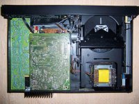
Below, I'm going to try to attach a photo of the inside of the machine. You can't see much because there are extra PCBs attached upside down over the main board. I've tried to get the biggest of these off but it seems stuck even though I've taken all the screws out. I'm afraid of damaging something by forcing it.
Anyway, I just wondered if the picture might jog any memories. Outside, it looks very much like the PCM 7000 (perhaps Audiofirst will confirm). The case is all plastic except for metal panels on the bottom, which I think are for reinforcement, and the metal lid. There's no mention of Cyrus anywhere on the machine, back or front, only Mission. Oddly, though, the serial number begins with a C, which is a characteristic of Cyrus equipment. It was manufactured in 1988.
Attachments
rwtomkins said:Thank you, Carawu. I thought the PCM II was just a re-badged Philips but maybe there's more Mission in there than I thought.
Below, I'm going to try to attach a photo of the inside of the machine. You can't see much because there are extra PCBs attached upside down over the main board. I've tried to get the biggest of these off but it seems stuck even though I've taken all the screws out. I'm afraid of damaging something by forcing it.
Anyway, I just wondered if the picture might jog any memories. Outside, it looks very much like the PCM 7000 (perhaps Audiofirst will confirm). The case is all plastic except for metal panels on the bottom, which I think are for reinforcement, and the metal lid. There's no mention of Cyrus anywhere on the machine, back or front, only Mission. Oddly, though, the serial number begins with a C, which is a characteristic of Cyrus equipment. It was manufactured in 1988.
Basically it's a Philips but the left light green board is NON-Philips.
Thanks again, guys. I asked Cyrus if they could tell me any more about the PCM II and they have just replied as follows:
"The PCMII was based on a Philips CD660 player although a vast amount of re-design was carried out by Mission the main difference between the PCM4000/7000 was that it included features such as phase invert and better track selection. It was introduced in January 1988 to replace the PCM7000 and it used the TDA1541P Dual 16 Bit DAC, early models used the CDM2 mechanism although later models used the CDM4. Unfortunately
we do not have circuit diagrams for this unit anymore."
Looks like you were right the first time, carawu!
Never heard of the TDA1541P before. Since I thought it had a TDA1541A, this comes as a bit of a disappointment. Should it?
Can anyone tell from the picture whether I have the CDM2 or the 4?
I find it quirky that manufacturers such as Mission etc don't archive their service data. For example, Musical Fidelity doesn't appear to have data for the A1 in their web archive, a product which (arguably) put them on the map. You could understand if it was, say, Akai or Teac in the mass market putting out hundreds of products. I suppose the obvious answer is obsolescence?
All this is relevant when you want to maintain a product that you love, such as a PCMII or PCM7000, Cyrus1 etc. Without access to the knowledge base in this fabulous forum, there would be little hope of resurrection for these iconic products.
Just my thoughts.
Blake
All this is relevant when you want to maintain a product that you love, such as a PCMII or PCM7000, Cyrus1 etc. Without access to the knowledge base in this fabulous forum, there would be little hope of resurrection for these iconic products.
Just my thoughts.
Blake
")
Thanks again, guys, please keep it coming. Meanwhile I think I may have found some schematics for the Philips CD 650. Have you seen this guy's website on modifying the 650? (Yes, I know, probably someone here!) It's half in German, half in English. If you scroll down to the section headlined Schema's, there are some diagrams for the CD 650 that seem to cover some or all of the bases. Just click your cursor on the diagram if it's not legible first time.
Hope they're some use.
http://www.stockhammer.at/hifi/cd650.php
Btw, I see from this that the 650 also employs the TDA1541P. Anyone know how this DAC compares with the TDA1541A?
Hope they're some use.
http://www.stockhammer.at/hifi/cd650.php
Btw, I see from this that the 650 also employs the TDA1541P. Anyone know how this DAC compares with the TDA1541A?
rwtomkins said:Thanks again, guys, please keep it coming. Meanwhile I think I may have found some schematics for the Philips CD 650. Have you seen this guy's website on modifying the 650? (Yes, I know, probably someone here!) It's half in German, half in English. If you scroll down to the section headlined Schema's, there are some diagrams for the CD 650 that seem to cover some or all of the bases. Just click your cursor on the diagram if it's not legible first time.
Hope they're some use.
http://www.stockhammer.at/hifi/cd650.php
Btw, I see from this that the 650 also employs the TDA1541P. Anyone know how this DAC compares with the TDA1541A?
Hey, wow. Some project! At some stage or other I'm sure I've had a CD650. Superb unit. Good luck with yours, rwtomkins!
If you look at the photos of the CD650 in the German article - you will notice that there is no "P" on the TDA1541.
I have never seen a "P" printed on any TDA1541 chip or datasheet. Is it possible tha the "P" is used by chip vendors and OEMs to indicate that it is a Philips chip? However, "P" is sometimes seen on other Philips chips like TDA1540, SAA7210 and SAA7220.
The Datasheet and packaging for the later TDA1541A version includes "N2" in the naming - but this is never printed on the chip. As far as I am aware, there are only six forms of this chip:- TDA1541, TDA1541 S1, TDA1541A, TDA1541A R1, TDA1541A S1 and TDA1541A S2. The first two are from the original design and manufacturing process of this chip. The next four (with "A" included) are from the revised design and manufacturing process - with higher specs. The suffix "S1" and "R1" indicate the grading according to linearity. The final one with "S2" is from a later production and has greater linearity. There is a variety of opinions on which version sounds best.
Now - to confuse the CD650 vs PCM7000 saga a bit more......my PCM7000 has TDA1541A S1 as standard......so don't be surprised if the PCMII has something other than a plain TDA1541 in it.
There are examples of similar CD players that appeared with a variety of different mechanisms and chips throughout their production cycle. Some started production with CDM2/10 or CDM2/29 and ended up with CDM4/11 or CDM4/12....as others started out with TDA1541 and ended with TDA1541A. It all depends on where they were in the production run, their stock levels and the timing of a change in the manufacture of Philips components.
That's really informative, Fin, thanks so much.
I only suggested the the CD 650 had a TDA1541P because that's what the German site said in the text, but as you rightly point out, the pictures tell a different story.
I'll let you know what's inside my PCM II as soon as I've taken it apart. Meanwhile, I've got an old magazine review of the PCM II on its way (hard copy) and I'll post anything interesting it might have to impart.
stoolpigeon said:I have two PCMII and both have standard TDA1541A.
That's very reassuring, stoolpigeon. Listen, this is very embarrassing but I'm just a beginner and I can't even get the top PCB out to see what's inside. It seems to be stuck to the "radiator" at the back of the PCM II even after I've taken the screws out and I can't see how or why. I'm afraid of doing serious damage by just blundering blindly on so I just wondered if you could give me any tips as to how to get the top PCB off.
The voltage regulators on the pcb are attached to the heatsink (radiator) so the pcb with heatsink needs to come out as 1 piece. I can't remember exactly but I think the heatsink pokes out the back panel so you will have to jiggle the assembly toward the front and then lift it out.
If you still have problems let me know and I can dig out my machine.
If you still have problems let me know and I can dig out my machine.

OK I just checked the thread and refering to the photo in your post #23 I think you need to remove the 2 screws at the front of the pcb in line with the tray loading motor and the screw on the heatsink which is not actually on the pcb. You should then be able to jiggle the assembly and pull it out. Note there are quite a few wires attached to the board but they are long enough to allow you to get the assembly out to see whats going on.
- Status
- This old topic is closed. If you want to reopen this topic, contact a moderator using the "Report Post" button.
- Home
- Source & Line
- Digital Source
- Philips cd650, Mission PCM7000 differences ?