Re: Re: Re: Re: Re: Re: This may work ........
Hi.
It may be necessary to add a regulator to ,say, 125V to reduce off load voltage and voltage droop in use.
Andy
JeroenR said:
Yep, That's the one.
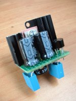
I used 47mF/160V caps as I was expecting 100V, not 150. Bit tight this way but at least it keeps the supply small. The red wire is the V-out. It is slightly boxed (alu) because it is close to outputs and the decoder/servo boards.
The decoder board is now empty where the opamps etc were. I hope to have just enough space for the tubes, caps and more caps...... and let's not forget the 6.3V supply.
Hi.
It may be necessary to add a regulator to ,say, 125V to reduce off load voltage and voltage droop in use.
Andy
Re: Re: Re: Re: Re: Re: Re: This may work ........
Why do you think that is necessary to add the regulator? Not enough head-room? I expect the tube circuit to draw about 1W (two time about 5mA at 100V) max.
Would someting like a 24reg and 100V zeners do the trick? But would that not require extra caps (space again)?
poynton said:
Hi.
It may be necessary to add a regulator to ,say, 125V to reduce off load voltage and voltage droop in use.
Andy
Why do you think that is necessary to add the regulator? Not enough head-room? I expect the tube circuit to draw about 1W (two time about 5mA at 100V) max.
Would someting like a 24reg and 100V zeners do the trick? But would that not require extra caps (space again)?
Re: Re: Re: Re: Re: Re: Re: Re: This may work ........
Exactly what I had in mind. The extra caps do not need to be huge - 47uF again
JeroenR said:
Why do you think that is necessary to add the regulator? Not enough head-room? I expect the tube circuit to draw about 1W (two time about 5mA at 100V) max.
Would someting like a 24reg and 100V zeners do the trick? But would that not require extra caps (space again)?
Exactly what I had in mind. The extra caps do not need to be huge - 47uF again
Re: Re: Re: Re: Re: Re: Re: Re: Re: This may work ........
Could I put a dummy load on the supply to simulate the power consumption and so see what voltage drop I can expect before I install the reg? I expect the tube-circuit will draw somewhere between 5 and 10mA per channel so perhaps a 20Kohm/5W to see what happens? Or will this do bang again?
I'm asking because I'm afraid that if I set the output to high (150V) then there will be not enough "room" for the reg and when I set the output too low (at 100V) there will be too much dissipation in the reg.
So perhaps the question is : how do I find out what the best value for the zener is?
Thanks,
Jeroen
poynton said:
Exactly what I had in mind. The extra caps do not need to be huge - 47uF again
Could I put a dummy load on the supply to simulate the power consumption and so see what voltage drop I can expect before I install the reg? I expect the tube-circuit will draw somewhere between 5 and 10mA per channel so perhaps a 20Kohm/5W to see what happens? Or will this do bang again?
I'm asking because I'm afraid that if I set the output to high (150V) then there will be not enough "room" for the reg and when I set the output too low (at 100V) there will be too much dissipation in the reg.
So perhaps the question is : how do I find out what the best value for the zener is?
Thanks,
Jeroen
poynton said:Try without the reg. to start.
It may be necessary to revise the power supply if too much hum.
Andy
I certainly will try this weekend. After the supply there will be a resitor and one more cap directly connected to the plate of the top tube so perhaps if I take a good cap, add a choke somewhere.....
I'll get back again with diagram and photo's later.
")
Thanks,
Jeroen
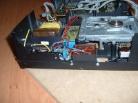
JeroenR said:Deforrestation........ room for the tubes.
where is the heater Tx?
Andy
poynton said:
where is the heater Tx?
Andy
It's the black block in front of the cdm.
JeroenR said:
It's the black block in front of the cdm.
Good luck !
Do we call the fire brigade now or later ?
Andy
poynton said:
Good luck !
Do we call the fire brigade now or later ?
Andy
Uhhh... why?
poynton said:
Good luck !
Do we call the fire brigade now or later ?
Andy
Come on Andy, the suspense is killing me.
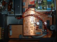
Are the tracks too close? Shouldn't I put the tx's parallel?
JeroenR said:
Come on Andy, the suspense is killing me.
Are the tracks too close? Shouldn't I put the tx's parallel?
It was a Joke !
poynton said:
It was a Joke !
You .......
New to this as I am I really spent some time thinking and rethinking what I did wrong.
And... it works. I can regulate with the pot to 6.3V. Still have to try with load though.
My 104 doesn't like CD-R`s, no proplems with orig. disc's. Have cleaned the lens, blackened the transport chassis inner surface. Any more hints on improving this? Seems it doesn't improve when burning slower, have tried 2 different recorders and various disc brands... It's odd, it's playing all orig. discs, no matter how dirty and scratchy they are... Thanks guy's!
Thanks Bernhard, I've already tried this. I think the problem is created by those old Electrolytics, as there's a lot of hum on the Power supply rails (~200mVpp).
It doesn't even recognize the cd-r's - no TOC redout....
Will replace them and try it again.
The eye pattern looks very blurred, might originate to the noisy power supply ...?
Markus
It doesn't even recognize the cd-r's - no TOC redout....
Will replace them and try it again.
The eye pattern looks very blurred, might originate to the noisy power supply ...?
Markus
- Home
- Source & Line
- Digital Source
- Philips CD104 tweaks