In my opinion, output capacitors that are polarized at 1/2 the supply rail, do not sound bad. I have a dynakit ST120 with output capacitors, and with the djoffe bias current modification, it sounds at 1.5 Vpp average exactly like a Peavey CS800s which has no capacitors in the sound path at all. What could sound bad of this primitive circuit is the poor control of output transistor bias current, leaving the transistors switching on and off (class B) at low volume. Also the idle current of the input transistors is not well controlled over temperature. The advantage of the output capacitor, when the circuit overheats and blows up, it doesn't take a $150 speaker with it by putting DC on the speaker. Other speaker protection circuits require dozens of parts to work correctly in an emergency, and I own another split supply amp (PV-1.3k) where they did not protect the speaker due to design faults.from your post I get it that just because u have the PCB, u want to assemble it. Remember in today's standards, this circuit stands nowhere. One reason is that it uses a single supply which needs an output capacitor for coupling the speaker.This sounds bad. I can see other reasons also but I am not competent enough to explain.
I'm fooling with the Salas G-amp which can use 2n3055 or MJ15015 if one wants to drill that many holes, or MJL4281 or 2SC5200 if one prefers drilling only one hole per transistor. http://www.diyaudio.com/forums/solid-state/229120-g-amp.html It is about the simplest 35 W/ch discrete transistor design IMHO that might have good sound and not much tendency to thermal runaway. There is nothing wrong with the 2n3055 or any of those other transistors for a low power amp. I was going to build ST120 copies, but the djoffe bias control circuit has 8 transistors and is a nuisance to build on perfboard. Single input transistor is fine, IMHO, if you have a star grounding system and don't have to reject power line hum coming in on the ring of the RCA cable. People have simulated the ST120 design and gotten distortion levels under .1% when the unit is warm enough. My $300 each SP2-XT speakers have more distortion than that, and they are the best I have ever heard.
LM3886 IC amps are potentially simpler than this amp, but I haven't figured out how to get the heat sink wafers without buying an amp kit yet. The package is allegedly TO220 but is not really, the TO220 heatsink washers aren't big enough. The LM3886 can use an output capacitor that is always charged up, and has internal short circuit protection. See the datasheet on datasheetcatalog.com.
Last edited:
I had built this amplifier taking care of all the precautions as prescribed in the book and was able to create the best sound system(Bolton 10 inch 60W woofer, 5inch 50W midrange and Philips Dome tweeter, and Philips crossover network, all 8 ohm) . The best part of the system is the bass which you can hear at the lowest volume. The best way to stop any hum sound or any distortion is to keep wiring as small as possible secondly shield the Preamp from mains transformer, Earthing loops must be avoided and do proper earthing as indicated in the book by MD Hull I had built this amplifier in 1996 which to date is running in perfect condition without any distortion. Make sure layout of the amplifier must be proper. Enjoy the sound.I have done what exactly stated at the book by M.D. Hull both preamplifier and Amplifier ckt but there is motorboting sound in no signal condition please give me a remedy.......
Is there any problem with BD139 & BD 140 matching hfe?????????
I use 2N3055 as output
Are you using the stabilized power supply. If the power supply is stabilized one you will not have any sound distortionI have done what exactly stated at the book by M.D. Hull both preamplifier and Amplifier ckt but there is motorboting sound in no signal condition please give me a remedy.......
Is there any problem with BD139 & BD 140 matching hfe?????????
I use 2N3055 as output
Hi
This circuit is my version of a pretty standard complementary single-ended 40W amplifier.
It builds on a number of ideas discussed by Bailey, Gibbs and Shaw. Bailey presented a complementary amplifier in 1968 in Wireless World and Gibbs and Shaw published a version using the cascode pre-driver stage in Practical Electronics in 1971.
It represents a step function improvement on the Mullard/Philips circuits in the following:
(1) the input stage uses a low impedance bias network which reduces LF noise with high input impedance sources (the input impedance however is low at ~20k)
(2) The pre-driver cascode circuit eliminates Early voltage distortion that Bailey was very concerned about
(3) The output stage uses classical complementary pairs, with base-to-base resistor to prevent crossover currents from the drivers (and maybe speed up turn-off of the output)
(4) frequency compensation is achieved with a 100pF input capacitor to ground and a 220pF loop compensation that avoids the Miller capacitor.
Simulated distortion is 0.022% at 10kHz.
If this amp oscillates then it will usually be cured with a "sprog. stopper" capacitor of 220pF between the base of the PNP driver and ground.
It is possible that this could be built on a PCB for the Philips circuit with some simple modifications.
Regarding motorboating: check with an oscilloscope if this is LF oscillation or "sprogging" due to HF oscillation. If HF then you will need to increase the pre-driver transistor base-to ground capacitor to e.g. 22nF or increase the Miller capacitor.
Poor bass response is due to the feeble output capacitors. Despite the PHilips circuits having feedback resistors from the outside of the output capacitor the weak value seriously limits LF perforamnce.
Although I have shown only the classical 2.2mF (=2200uF) at least 10mF is really needed - and 22mF for good bass.
Regards
John
Attachments
Poor bass response is due to the feeble output capacitors.
Revert R17 and C6 such that it s the resistor that goes to ground
and then pick the output through a FB resistor that goes to the
common point of thoses two components.
This feedback resistor should be equal to R2 , this will ensure
good enough bass response , to keep the same gain you ll have
to use two 3k resistors of course.
Hi Wahab
This only works in small signal mode. Nothing can compensate for a small capacitor at full drive at low frequencies - try simulating a square wave. Even the droop at 20Hz is poor with 2.2mF, and if you split the feedback as you suggest it may reduce this effect at low powers, but the output capacitor voltage increases to keep the output constant. So the amp will not be able to deliver full power at low frequencies even with a split feedback.
I think it is better to use a bigger capacitor, to avoid low frequency transients from sounding "empty" if insufficient power is available, or the bass may be "artificially boomy" with a capacitor recovery overshoot. The point is, the capacitor voltage should not change with a signal. This needs a big capacitor! (Or none, as most amps are now directly coupled).
John
Hi John,
Thanks for modifying the venerable Philips amp !
Few queries: (i) Is the bias current through output devices fixed? (ii) Since the extra current required during high amplitude signals will be provided by the (large) power supply reservoir capacitors, is it really necessary that C1 should be as high as 2.2mF? (iii) How does the decrease of input impedance to 20 K affect the overall sound?
Thanks,
Reji
Hi
This is a class AB amp which means that the quiescent current should be enough to minimise crossover distortion. Typically 50-100mA. Usually adjustable bias resistors are used to set this but you can trim fixed resistors with extra resistors in parallel.
2.2mF was a common value (used in many amps in the 70's) but is not enough for low bass. You can think of this as a minimum. My point was that feedback from the outside of the capacitor is worse at low frequencies and high output levels than feedback inside from the output (mid) rail, and reasonable performance is possible even with 2.2mF - it depends how "strong" you like the bass...and whether your loudspeakers work well at low frequencies. If you only run "bookshelf" or small speakers with a respose to about 80Hz you may not notice the difference with larger capacitors!
The lower input impedance should not affect performance, as this depends largely on the preamplifier output impedance. The input resistor of 1kohm may have more influence but is intended to reduce slew rate distortion and RF pick up. The input capacitor is added for stability: again, if a preamp is connected then this may not be required for stability reasons but may help for reducing high frequency (transient) distortions.
John
Hi All New version (modification) of this old amplifier
 Mr Seetharaman Subramanian made modification of this old Phillips 40watts amplifier
This versatile amplifier circuit is designed and submitted by Mr Seetharaman Subramanian from Chennai . The full credit of this article goes to him and we are very proud to publish this fabulous circuit here.
Seetharaman’s description about the circuit.
This concept has appeared long back in Practical Electronics a UK based Magazine. Based on this concept I designed this circuit during 1981 to 1986 with lots of field trials and modifications, the design was frozen in 1986. I have assembled so many amplifiers for me and for my friends based on this design with various power levels. They are still kicking in so many houses. This concept can be applied to any existing amplifier also. You must listen to believe the crystal clear thumping bass response. crystal clear mid and hi frequencies. Good transient response with very low distortion. Hope you guys will enjoy the reproduction of this amplifier.
In the art of audio sound reproduction it is well-known that the dynamic loudspeaker is more nonlinear and generates more distortion than all the other system components combined. This is particularly true at low frequencies which require large cone excursions where the stiffness of both the inner spider and the outer surround increases rapidly as the cone approaches its peak displacement, resulting in a nonlinear suspension compliance generating high distortion.
For example, in a typical high fidelity sound system at a frequency of about 35 Hz the total harmonic distortion of the amplifier might be of the order of 0.01%, whereas the distortion of the loudspeaker might range from about 3.0% to about 50.0%, depending upon the loudness. If this cone motion can be sensed and given as a feed back to the earlier stage of the amplifier, this distortion can be reduced dramatically.
Motional Feedback (MFB) was a speaker system developed in the early 1970s by Philips Holland. It introduced a feedback system to the woofers of HiFi loudspeakers, enabling them to achieve a more extended low frequency response in a relatively small enclosure. The key benefits are a very controlled bass response. Any distortion induced by the enclosure or the woofer itself is immediately corrected by the feedback. These hand-built speakers were sounding very good and were quite expensive.
As a different approach, instead of using the cone movement, the current flow through the voice can be sensed (the current is proportional to cone movement) and can be used as a cone movement feedback. This novel idea is used in this amplifier design (I don’t claim any originality; this idea has appeared in Practical Electronics UK Magazine – long back – They might have even patented it).
The amplifier used here is a standard Philips audio application circuit, with a specification of 40 Watt RMS @ < 0.06% Total Harmonic Distortion into 8 ohms impedance speaker and having a frequency response from 20Hz to 100 KHz, suitably modified for our application.
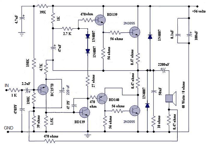
The amplifier is a conventional class B directly coupled quasi complimentary out put stage, operating with single 56Volt supply (no need for a regulated or dual power supply). BC157 is the pre-driver and half supply stabilizer. BD 139 is the driver, a BD139 and a BD140 complimentary pair out put driver stage with 2N3055 as final out put stage. The speaker voice coil current is sensed through 0.47 ohms resistance connected from speaker one end to ground. This signal is given as negative fed back to previous stage through 470 ohms. The half supply at speaker coupling capacitor can be adjusted by varying the 39K resistance (if required you may fix a 100K pre set in the place of 39K and adjust for half supply with no in put signal at junction of both 0.47 ohms of out put transistors and speaker coupling capacitor). The quiescent current through output transistors can be adjusted with 22 ohms in series with two bias diodes 1N4007. The value for 50mA quiescent current will lie between 15 to 33 ohms for a supply of 56volts. The amplifier can be protected with a simple 1.5Amp fast acting fuse in the positive power supply.
The amplifier can be assembled on 40watt Philips amplifier application board or on any standard plain straight line board. All the three driver transistors require cooling clips. (Standard TO220 casing cooling fins). Out put transistors require a good quality extruded alloy heat sink with insulating mounting kit and with a smear of silicon conductive grease, for good conductance of heat.
The recently appeared passive Bass/Treble tone control with 12volt supply in “Circuits Today” as Baxendall tone control circuit is the most suitable preamplifier and tone control for this amplifier.
Circuit diagram
This versatile amplifier circuit is designed and submitted by Mr Seetharaman Subramanian from Chennai . The full credit of this article goes to him and we are very proud to publish this fabulous circuit here.
Seetharaman’s description about the circuit.
This concept has appeared long back in Practical Electronics a UK based Magazine. Based on this concept I designed this circuit during 1981 to 1986 with lots of field trials and modifications, the design was frozen in 1986. I have assembled so many amplifiers for me and for my friends based on this design with various power levels. They are still kicking in so many houses. This concept can be applied to any existing amplifier also. You must listen to believe the crystal clear thumping bass response. crystal clear mid and hi frequencies. Good transient response with very low distortion. Hope you guys will enjoy the reproduction of this amplifier.
In the art of audio sound reproduction it is well-known that the dynamic loudspeaker is more nonlinear and generates more distortion than all the other system components combined. This is particularly true at low frequencies which require large cone excursions where the stiffness of both the inner spider and the outer surround increases rapidly as the cone approaches its peak displacement, resulting in a nonlinear suspension compliance generating high distortion.
For example, in a typical high fidelity sound system at a frequency of about 35 Hz the total harmonic distortion of the amplifier might be of the order of 0.01%, whereas the distortion of the loudspeaker might range from about 3.0% to about 50.0%, depending upon the loudness. If this cone motion can be sensed and given as a feed back to the earlier stage of the amplifier, this distortion can be reduced dramatically.
Motional Feedback (MFB) was a speaker system developed in the early 1970s by Philips Holland. It introduced a feedback system to the woofers of HiFi loudspeakers, enabling them to achieve a more extended low frequency response in a relatively small enclosure. The key benefits are a very controlled bass response. Any distortion induced by the enclosure or the woofer itself is immediately corrected by the feedback. These hand-built speakers were sounding very good and were quite expensive.
As a different approach, instead of using the cone movement, the current flow through the voice can be sensed (the current is proportional to cone movement) and can be used as a cone movement feedback. This novel idea is used in this amplifier design (I don’t claim any originality; this idea has appeared in Practical Electronics UK Magazine – long back – They might have even patented it).
The amplifier used here is a standard Philips audio application circuit, with a specification of 40 Watt RMS @ < 0.06% Total Harmonic Distortion into 8 ohms impedance speaker and having a frequency response from 20Hz to 100 KHz, suitably modified for our application.
The amplifier is a conventional class B directly coupled quasi complimentary out put stage, operating with single 56Volt supply (no need for a regulated or dual power supply). BC157 is the pre-driver and half supply stabilizer. BD 139 is the driver, a BD139 and a BD140 complimentary pair out put driver stage with 2N3055 as final out put stage. The speaker voice coil current is sensed through 0.47 ohms resistance connected from speaker one end to ground. This signal is given as negative fed back to previous stage through 470 ohms. The half supply at speaker coupling capacitor can be adjusted by varying the 39K resistance (if required you may fix a 100K pre set in the place of 39K and adjust for half supply with no in put signal at junction of both 0.47 ohms of out put transistors and speaker coupling capacitor). The quiescent current through output transistors can be adjusted with 22 ohms in series with two bias diodes 1N4007. The value for 50mA quiescent current will lie between 15 to 33 ohms for a supply of 56volts. The amplifier can be protected with a simple 1.5Amp fast acting fuse in the positive power supply.
The amplifier can be assembled on 40watt Philips amplifier application board or on any standard plain straight line board. All the three driver transistors require cooling clips. (Standard TO220 casing cooling fins). Out put transistors require a good quality extruded alloy heat sink with insulating mounting kit and with a smear of silicon conductive grease, for good conductance of heat.
The recently appeared passive Bass/Treble tone control with 12volt supply in “Circuits Today” as Baxendall tone control circuit is the most suitable preamplifier and tone control for this amplifier.
Circuit diagram
Last edited:

with ref to the pic above the output transistors were mounted externally, another amp that was also popular at that time was based on that published in ETI magazine, uses dual supply & TIP3055 & TIP2955 w/o of course coupling capacitor at the output, comaped to PHILIPS this was better and can go upto 100WATTS RMS with additional pair of transistors.
Not with low voltage transistors like 2N3055......can any one have High power circuit more than 80 watts in to 8ohm load based on same design....
You need higher voltage transistors and (expensive) capacitors throughout. A pair of 2SC5200 output transistors will produce 80W/8R but require an 85-100V rail, depending on the transformer rating and quality.
Most offers of designs referring to higher power like 100W from 2N3055 transistors forget to tell you that to do that, you need to lower the speaker impedance to 4R so that parallel pairs can deliver 100W where otherwise, simply they can't.
- Home
- Amplifiers
- Solid State
- Philips 40/25/15 watts amplifier with Universal preamplifier circuit.