OK. And I assume the collector of 6404 was at a similar level .
Quick question. How does the level of signal on the lead compare with the good channel ? Is the voltage level on the other channel a lot higher ?
(The overall gain of the circuitry is around 27 numerically. That means you need around 700 millivolts or so to drive the speaker fully. The 36 millivolts we have is proving up to now that there is no problem as far as we have gone... in other words what we see at the input is getting passed along correctly, all assuming the 6404 result was good of course)
Just realised you required c Collector for 6404
440 Hz test tone Sensitive control to full on pre-amp, 6404 collector .009 vac,
The 440 Hz test tone Sensitive control to full on pre-amp, 6404 emitter .002 vac, is this way too low/bad?
I can check the signal output from the other channel if you like, I would expect it to be the same, its just a case of swapping over the leads?
The level on 6404 collector should be in the same ballpark as you see on those first two transistor emitters. Remember that if you have altered any controls on the preamp such as balance or master volume then the levels will all change.
So if you have 0.009 vac on 6404 you should have around that back at 6400 and 6401 emitters.
So if you have 0.009 vac on 6404 you should have around that back at 6400 and 6401 emitters.
Michael, we'll have to continue later. I wonder if something odd is going on at the front end. Don't assume or discount anything. Swap the lead over.
Things for you to check and compare...
1/ It is definitely worth checking the signal voltage on both output leads from the preamp. Make sure you set the balance to the centre position and play the tone. It should be equal on both leads.
2/ If the above is OK then we have to consider that if there were a problem with the preamp not being able to deliver 'current' into the load the speaker circuitry presents. That would drop the level we see.
The only way to easily check that is simply to connect the good speaker to the lead we are working with now. The good speaker should work as normal. Make sure you set all the controls and switches to match the good speaker.
Ultimately you need around 700mv or so to drive the speaker to its maximum. We are a long way off that but that is because we aren't seeing that kind of voltage coming from the preamp. The test tone should be at quite a high level and through the good speaker be very very loud if you turn it up.
That is in the right sort of region for that stage. I can prove that with a simulation of the circuit.
Go through what I list in the post above and also see what this shows,
With both leads disconnected, how much signal can you get from the preamp as you turn up the volume ? You should be able to achieve around the 700mv region.
Every single test we have done comes back time after time that the circuitry is passing the signal OK. What we aren't seeing is sufficient signal right at the input.
Have tested left and right channels for signal voltage our side (right) now reads .033vac (before .026vac) left reads .024vac. Did not turn up the volume because I would lose this setting and the buss is already loud (did you know the sound becomes quite when the sensitive control is over to speaker amp).
Mark and you say; the sensitive control has to be full on pre-amp for this testing and we have it on this setting, is this still the case for fault finding? If it is on pre-amp would the speaker amp come into use; logic would say no?
If you look at post 207 the sensitive control was on full speaker-amp (this is where it is usually left, using the speaker amp full on); you noticed the signal had gone, surely we can work from here again to find the fault?
To recap; we have .033vac on the signal lead so we should be looking for .330vac after the speaker amp comes alive; which it is not coming alive?
I still hope we can nail this... lets be sure we are understanding each other on basic settings and so. Maybe I have made some assumptions along the way so lets be 100% sure and then we are not backtracking. Read through this slowly and go through the steps methodically one at a time making sure the result is as expected.
Although it might not look it they are close enough but there is not enough voltage there to drive the speaker anywhere near fully.
My understanding of the terms used here (without having seen one of these units for real) is that 'speaker amp' means using an input that has already been amplified to speaker level. The pre-amp setting I would take to be the most sensitive and the one to use when coupled to your preamplifier.
So it becomes quiet when turned to 'speaker amp' because it is expecting far more input voltage than the preamp can provide.
To eliminate any possible confusion here you must set the controls and switches on the faulty speaker to match those on the known good one. If you do that then there is no possibility of error or misunderstanding.
So lets get this right and make every action count towards the goal of fixing it")
1/ I want you to set the balance control on the preamp to the centre position and then get your good speaker working normally.
2/ Set and turn all the user controls on the faulty speaker to match those of the good one. That eliminates any misunderstanding of which way to turn or set things.
So far so good. You should have one speaker that plays normally and I assume one that does not. From this point on the only control you will alter will be the main volume on the preamp.
3/ Now prove to yourself (and me) that the fault remains on the same speaker if you swap the input leads over.
I now want to know just how much voltage that preamp puts out. The reason for asking this is so I know for 100% certain that the level from the test tone is as expected. It should be able to drive the speakers to very loud levels. I've 'assumed it does up to now, so now I want it proving by measurement.
4/ Turn off both speakers and disconnect the leads from the preamp. Now turn the volume on the preamp up while measuring the signal at the end of the leads.
What voltage does it go up to ???? You should see at least somewhere around 0.4 volts or more (at a guess considering the level of the tone). It is very important to prove that is so. Both leads should be the same give or take.
5/ Now turn the preamp volume down and couple up the faulty speaker.
The above covers the basics and ensures both speakers are set the same. It tells us that the preamp and leads are OK. It also tells us the test tone is available at a sufficient level to fully drive the speaker.
---------------------------------------------------------------------------------------
Knowing all that we can now measure the voltage on point C402 and turn the preamp volume up to give a known level which can decide on. Lets say 0.1 volts.
Lets get to this point and see where we are at
Have tested left and right channels for signal voltage our side (right) now reads .033vac (before .026vac) left reads .024vac.
Although it might not look it they are close enough but there is not enough voltage there to drive the speaker anywhere near fully.
Did not turn up the volume because I would lose this setting and the buss is already loud (did you know the sound becomes quite when the sensitive control is over to speaker amp).
My understanding of the terms used here (without having seen one of these units for real) is that 'speaker amp' means using an input that has already been amplified to speaker level. The pre-amp setting I would take to be the most sensitive and the one to use when coupled to your preamplifier.
So it becomes quiet when turned to 'speaker amp' because it is expecting far more input voltage than the preamp can provide.
To eliminate any possible confusion here you must set the controls and switches on the faulty speaker to match those on the known good one. If you do that then there is no possibility of error or misunderstanding.
So lets get this right and make every action count towards the goal of fixing it
1/ I want you to set the balance control on the preamp to the centre position and then get your good speaker working normally.
2/ Set and turn all the user controls on the faulty speaker to match those of the good one. That eliminates any misunderstanding of which way to turn or set things.
So far so good. You should have one speaker that plays normally and I assume one that does not. From this point on the only control you will alter will be the main volume on the preamp.
3/ Now prove to yourself (and me
) that the fault remains on the same speaker if you swap the input leads over.I now want to know just how much voltage that preamp puts out. The reason for asking this is so I know for 100% certain that the level from the test tone is as expected. It should be able to drive the speakers to very loud levels. I've 'assumed it does up to now, so now I want it proving by measurement.
4/ Turn off both speakers and disconnect the leads from the preamp. Now turn the volume on the preamp up while measuring the signal at the end of the leads.
What voltage does it go up to ???? You should see at least somewhere around 0.4 volts or more (at a guess considering the level of the tone). It is very important to prove that is so. Both leads should be the same give or take.
5/ Now turn the preamp volume down and couple up the faulty speaker.
The above covers the basics and ensures both speakers are set the same. It tells us that the preamp and leads are OK. It also tells us the test tone is available at a sufficient level to fully drive the speaker.
---------------------------------------------------------------------------------------
Knowing all that we can now measure the voltage on point C402 and turn the preamp volume up to give a known level which can decide on. Lets say 0.1 volts.
Lets get to this point and see where we are at
This is what you said about the Setup
Take it slowly and logically. The starting point is the voltage on C402. Then with the sensitivity control on full (as you normally use it) you measure on the transistor emitters. The level here will be quite a bit lower than at the input believe it or not. That's correct.
New test 440 Hz test tone sensitive control to full on pre-amp, C402 1.029vac (approx.), then connect power to speaker unit and turn on C402 voltage rapidly decreases to .029vac (approx.) isn’t this the problem
Just explain slowly what you are seeing and yes, if it is dropping to just 29 millivolts we appear to have a problem.
Two questions.
The 1.029 vac on C402 is plenty. Is that with the main volume control on the preamplifier turned up on full ?
Is it the action of turning the control 3400 on the speaker that is causing this voltage to fall ?
and yes, if it is dropping to just 29 millivolts we appear to have a problem.Two questions.
The 1.029 vac on C402 is plenty. Is that with the main volume control on the preamplifier turned up on full ?
Is it the action of turning the control 3400 on the speaker that is causing this voltage to fall ?
And more...
When you measure 1.029 vac on C402 what single step do you take that then causes that to fall to 0.029 vac ?
You say 'then connect power to speaker unit and turn on C402 voltage rapidly decreases to .029vac' .
If that is the only action you are taking i.e. switching the speaker on, then something is very wrong around that area.
This is what you said about the Setup
Take it slowly and logically. The starting point is the voltage on C402. Then with the sensitivity control on full (as you normally use it) you measure on the transistor emitters. The level here will be quite a bit lower than at the input believe it or not. That's correct.
New test 440 Hz test tone sensitive control to full on pre-amp, C402 1.029vac (approx.), then connect power to speaker unit and turn on C402 voltage rapidly decreases to .029vac (approx.) isn’t this the problem
1. The volume on the pre-amp is set at normal.
2. The voltage rapidly decreases when connecting the power to speaker unit and turn on; as simple as that.
That is very very odd in that case, and I'll be honest, that doesn't really make sense however we must work with your measured result and observations and pursue it.
1/ Just confirm that when the meter is showing 1.029 vac that if you then 'pause' or 'stop' the CD player that the meter then shows zero. (It has to do because you are removing the signal). Use the same measurement locations as you did before... keep everything the same.
Assuming the above is OK then I can't see any logical way that simply powering up the speaker can drop the signal at the input by the amount it is doing. There are a couple of weird scenarios that could do something like that so lets check those out.
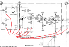
2/ Without disturbing anything put your meter on 'ohms' and check that there is direct continuity from the outer part of the input sockets to resistor 3405 and cap 2400. That is just to make certain the ground continuity is good. All the ground points on board B should be in direct contact with the input grounds as shown here. So all the grounds should be continuous C411, C401, A422 and C101 they all should read directly one to another and all should read directly to the input sockets.
If all that is OK then its getting really bizarre. We would then simply remove resistor 3406 to remove the possibility of anything happening on the input circuitry reflecting back and doing something strange. If something was reflecting back then the 1.029 vac should re-appear.
These checks have got to show a discrepancy somewhere. It can't pass these steps... it has to fall down at one of these.
1/ Just confirm that when the meter is showing 1.029 vac that if you then 'pause' or 'stop' the CD player that the meter then shows zero. (It has to do because you are removing the signal). Use the same measurement locations as you did before... keep everything the same.
Assuming the above is OK then I can't see any logical way that simply powering up the speaker can drop the signal at the input by the amount it is doing. There are a couple of weird scenarios that could do something like that so lets check those out.
2/ Without disturbing anything put your meter on 'ohms' and check that there is direct continuity from the outer part of the input sockets to resistor 3405 and cap 2400. That is just to make certain the ground continuity is good. All the ground points on board B should be in direct contact with the input grounds as shown here. So all the grounds should be continuous C411, C401, A422 and C101 they all should read directly one to another and all should read directly to the input sockets.
If all that is OK then its getting really bizarre. We would then simply remove resistor 3406 to remove the possibility of anything happening on the input circuitry reflecting back and doing something strange. If something was reflecting back then the 1.029 vac should re-appear.
These checks have got to show a discrepancy somewhere. It can't pass these steps... it has to fall down at one of these.
Attachments
What about this one; 2400 is an 180p capacitor (does p stand for plate?); Resistance test, once leads were connected a reading started to be displayed then went on to display 0.L (for none Fluke readers this means nothing being detected). Capacitance test; 00.35nf.
I made sure no volts were present before taking the latter test, is it a none polarized component?
The other checks were good; I think it would be good to make and submit a list of the components that have been checked with the results; so we would know which have been checked etc.; it would save time unless this is the fault.
It stands for 'pico' (10E-12) so it is a 180 picofarad capacitor, non polarised. Its function is to form a filter and help stop extreme high frequencies entering the unit (such as radio interference, taxis, that kind of thing). It can be removed as a check.
Michael, you say the other checks were good and yet it just has to fall down at some point during those steps.
So the 1.029 vac dropped to zero when you stopped the CD
The continuity of grounds and signal feed were confirmed good
You removed resistor 3406. Did the signal now re-appear back again at 1.029 vac ? or did it still fall to nearly nothing when you powered it up ?
Michael, you say the other checks were good and yet it just has to fall down at some point during those steps.
[/B]
New test 440 Hz test tone sensitive control to full on pre-amp, C402 1.029vac (approx.), then connect power to speaker unit and turn on C402 voltage rapidly decreases to .029vac (approx.) isn’t this the problem
This is what you said about the Setup
1. The volume on the pre-amp is set at normal.
2. The voltage rapidly decreases when connecting the power to speaker unit and turn on; as simple as that.
So the 1.029 vac dropped to zero when you stopped the CD
The continuity of grounds and signal feed were confirmed good
You removed resistor 3406. Did the signal now re-appear back again at 1.029 vac ? or did it still fall to nearly nothing when you powered it up ?
- Status
- This old topic is closed. If you want to reopen this topic, contact a moderator using the "Report Post" button.
- Home
- Amplifiers
- Chip Amps
- Philips 22AH587 replica modules