Those who retain an interest in this thread may wish to read “One Model to Rule Them All” in the March 2016 issue of audioxpress. This article presents a single “Unified Model” for predicting the gains, frequency responses, impedances and power supply rejections of three separate triode circuits: the voltage gain stage, the cathode follower, and the Cathodyne.
The Model’s derivation starts with the schematic of a triode with plate and cathode loads, grid bias and plate supply voltage. All component and parameter values at this stage are arbitrary. The triode is replaced with a small signal source using the parameters μ and rp. Kirchoff conservation of current equations are written at the plate and cathode, taking AC grid and power supply noise voltages into consideration. All DC signals are set to zero (courtesy of the Superposition Theorem), allowing us to concentrate on the AC audio signals. The equations are solved to produce one for the plate voltage and one for the cathode voltage. Each describes a circuit of its own: one from the point of view of the plate, and one from that of the cathode. Readily apparent with no further computations are the impedances rp + Zk•(μ+1) of the source driving and seen by the plate load Zp, and (Zp+rp)/(μ+1) of the source driving and seen by the cathode load Zk. These expressions can be evaluated by substituting parameter and component values from any particular circuit of interest, including a matched-load Cathodyne (MLC). For such a circuit, neither impedance is well-approximated by 1/gm. The complete equations and circuits are available in the article, along with confirmational bench test results and other discussions which relate to this long thread.
Those folks can rest easy who believe that the characteristics of an MLC cannot be determined by tests which disrupt that match. Nothing about the Model at any point connects anything to, removes anything from, or modifies the circuit being analyzed. However, it should be noted that the application of Thevenin in a manner which does disturb such a match yields exactly the same results as the Unified Model describes above.
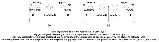
A final section discusses the problems with the currently popular models of the MLC (see attached). For any matched load pairs that you might choose, the models give contradictory and incorrect predictions of the impedances of the sources seen by the plate and cathode loads. As confirmed by a straight forward bench test, the same problems occur with power supply noise rejections at the plate and cathode when a simple noise source is inserted between ground and the plate load.
I hope that the approach described here and in the article can serve as a step toward a resolution of The Great Cathodyne Impedance Debate.
The Model’s derivation starts with the schematic of a triode with plate and cathode loads, grid bias and plate supply voltage. All component and parameter values at this stage are arbitrary. The triode is replaced with a small signal source using the parameters μ and rp. Kirchoff conservation of current equations are written at the plate and cathode, taking AC grid and power supply noise voltages into consideration. All DC signals are set to zero (courtesy of the Superposition Theorem), allowing us to concentrate on the AC audio signals. The equations are solved to produce one for the plate voltage and one for the cathode voltage. Each describes a circuit of its own: one from the point of view of the plate, and one from that of the cathode. Readily apparent with no further computations are the impedances rp + Zk•(μ+1) of the source driving and seen by the plate load Zp, and (Zp+rp)/(μ+1) of the source driving and seen by the cathode load Zk. These expressions can be evaluated by substituting parameter and component values from any particular circuit of interest, including a matched-load Cathodyne (MLC). For such a circuit, neither impedance is well-approximated by 1/gm. The complete equations and circuits are available in the article, along with confirmational bench test results and other discussions which relate to this long thread.
Those folks can rest easy who believe that the characteristics of an MLC cannot be determined by tests which disrupt that match. Nothing about the Model at any point connects anything to, removes anything from, or modifies the circuit being analyzed. However, it should be noted that the application of Thevenin in a manner which does disturb such a match yields exactly the same results as the Unified Model describes above.
A final section discusses the problems with the currently popular models of the MLC (see attached). For any matched load pairs that you might choose, the models give contradictory and incorrect predictions of the impedances of the sources seen by the plate and cathode loads. As confirmed by a straight forward bench test, the same problems occur with power supply noise rejections at the plate and cathode when a simple noise source is inserted between ground and the plate load.
I hope that the approach described here and in the article can serve as a step toward a resolution of The Great Cathodyne Impedance Debate.
Attachments
I've reviewed this article in detail, as well as digesting the Valley and Wallman reference, which I wish I'd found years ago (it comes up late in the book). I find Chris Paul's account unassailable, and his approach of considerable utility---although many people will just fall back on simulations when faced with design and analysis of circuits.Those who retain an interest in this thread may wish to read “One Model to Rule Them All” in the March 2016 issue of audioxpress. This article presents a single “Unified Model” for predicting the gains, frequency responses, impedances and power supply rejections of three separate triode circuits: the voltage gain stage, the cathode follower, and the Cathodyne.
The Model’s derivation starts with the schematic of a triode with plate and cathode loads, grid bias and plate supply voltage. All component and parameter values at this stage are arbitrary. The triode is replaced with a small signal source using the parameters μ and rp. Kirchoff conservation of current equations are written at the plate and cathode, taking AC grid and power supply noise voltages into consideration. All DC signals are set to zero (courtesy of the Superposition Theorem), allowing us to concentrate on the AC audio signals. The equations are solved to produce one for the plate voltage and one for the cathode voltage. Each describes a circuit of its own: one from the point of view of the plate, and one from that of the cathode. Readily apparent with no further computations are the impedances rp + Zk•(μ+1) of the source driving and seen by the plate load Zp, and (Zp+rp)/(μ+1) of the source driving and seen by the cathode load Zk. These expressions can be evaluated by substituting parameter and component values from any particular circuit of interest, including a matched-load Cathodyne (MLC). For such a circuit, neither impedance is well-approximated by 1/gm. The complete equations and circuits are available in the article, along with confirmational bench test results and other discussions which relate to this long thread.
Those folks can rest easy who believe that the characteristics of an MLC cannot be determined by tests which disrupt that match. Nothing about the Model at any point connects anything to, removes anything from, or modifies the circuit being analyzed. However, it should be noted that the application of Thevenin in a manner which does disturb such a match yields exactly the same results as the Unified Model describes above.
A final section discusses the problems with the currently popular models of the MLC (see attached). For any matched load pairs that you might choose, the models give contradictory and incorrect predictions of the impedances of the sources seen by the plate and cathode loads. As confirmed by a straight forward bench test, the same problems occur with power supply noise rejections at the plate and cathode when a simple noise source is inserted between ground and the plate load.
I hope that the approach described here and in the article can serve as a step toward a resolution of The Great Cathodyne Impedance Debate.
Well, doesn't the output impedance on both sides of the cathodyne stay the same with no current being drawn? That's my understanding. Isn't that the main impediment for getting exactly inverse voltage out from upper and lower. Also, everything being equal with other types of phase splitter one gets 2x voltage out for the same input voltage into the cathodyne.
Actually I misspoke. The impedances are different according to Morgan Jones. (Just reviewed what he wrote). Rather, if there is no current drawn in either upper or lower loads then there will be no voltage drop across both upper and lower (different) impedances. So, it won't matter and the output voltages will be equal. I'm not confident that one can keep grid current out of conventional tube loads on max signals. That's why I argued for a source follower. Both together is my favorite combination for the previous reasons.
I am very interested to hear that Mr. Jones is saying that the impedances are different, a claim with which I agree. I am more familiar with his claims to the effect that they are both equal and about 1/gm. In what reference does he say that they are different, and what does he say that they are?
Identical cathode or source followers buffering each cathodyne output will render its differences in output impedances pretty much inconsequential. But it won't address a bigger problem I'd be happy to discuss after you advise what Mr. Jones has to say.
Identical cathode or source followers buffering each cathodyne output will render its differences in output impedances pretty much inconsequential. But it won't address a bigger problem I'd be happy to discuss after you advise what Mr. Jones has to say.
Technically, you are right about him saying it's 1/gm on both. But he's only saying it for the case of no current draw on either load. I'm cutting him some slack because if you agree with him, or you don't agree with him, the effect of having no current draw has the effect of making the impedances on both loads equal, in that there won't be voltage drops on either impedance. So in my case I don't really care.
In the case of the second condition, current draw on the loads, he's saying the cathode load impedances and the anode load impedances are quite different. That's what I was quoting and that's what I care about.
In the case of the second condition, current draw on the loads, he's saying the cathode load impedances and the anode load impedances are quite different. That's what I was quoting and that's what I care about.
I am trying to understand your reasoning. If it is your own, then you have no need to mention Mr. Jones - you can, and should, justify it on your own. I would be happy to hear you do so.
But if your reasoning is based on the assumption that Mr. Jones' reasoning is correct, then you should care very much whether or not he is, right?
May we start again? Let's leave Mr. Jones out of the picture. What do you assert, and what do you question?
But if your reasoning is based on the assumption that Mr. Jones' reasoning is correct, then you should care very much whether or not he is, right?
May we start again? Let's leave Mr. Jones out of the picture. What do you assert, and what do you question?
Thing is, it's easy to demonstrate that the impedances on both sides of the cathodyne are very different and very much unequal to 1/gm (even though the voltages are equal and opposite) even if no current is drawn by the output tubes from the cathodyne. This can be demonstrated simply.
So if it is your understanding that the impedances are equal if no current is drawn, I must disagree.
So if it is your understanding that the impedances are equal if no current is drawn, I must disagree.
I still do hope for a conversation, exeric. But I have gotten used to a preference of some folks for simply accepting and not considering or even being willing to question certain things that have been stated in books by popular authors.
So, bypassing comment on certain derivative assumptions that you have stated, let's get to the matter of connecting source followers to Cathodyne outputs. I assume you mean the outputs of these followers to be capacitively coupled to the grids of the output tubes.
When output stage grid current is drawn due to signal peaks, these newly low impedance grids draw significant current which rapidly adds a new charge voltage to the coupling capacitors. When the peak signal and therefor the grid current goes away, only the high impedance grid bias resistors of the output stage are left to dissipate this charge. This can take quite some time. This leads to the so-called "blocking" effect.
A solution might be to capacitively couple the cathodyne outputs to the gates of (MOSFET) followers whose sources (outputs) are DC-coupled to the output stage grids. Those grids would still draw current on signal peaks, but the currents would be supplied by the MOSFETs and would not charge inter-stage coupling capacitors.
Yes, this is exactly my preference. Getting back to my original statement I started out with - I think that implementation is the cat's meow for both phase inversion and powerful control of the output tubes with minimal add-on effects. And because of doubling the Vout / Vin of cathodyne phase inversion over other 2 tube phase inversions it adds other possibilities too. For instance it is just made for PPP amplifiers with output tubes with small signal input requirements, e.g EL84 or 6v6, and using just one medium MU input voltage amplifying tube. You really don't have to worry about miller capacitance with many small signal amplifier power tubes in parallel in that setup, nor of course blocking distortion.
")
Last edited:
- Status
- This old topic is closed. If you want to reopen this topic, contact a moderator using the "Report Post" button.
- Home
- Amplifiers
- Tubes / Valves
- phase splitter issue