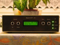
After 3 month I've finished my PGA2310 based preamp. Some technical data :
Digital part :
- PIC 16F628 running at 4MHz for volume and mute control and driving LCD display
- PIC 12F675 running at 1MHz for input selector
- 16x2 LCD with backlite
- PGA 2310
Analog part is based on the schematic from
This page . The only difference is that I used OPA2134 for input and output buffer.
Here is the front view
Attachments
Hi bostjancek,
Good job, looks good.
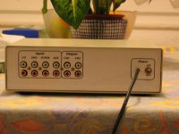
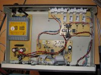
One thing: those unshielded cables should not be close to each other, it creates crosstalk.
Most critical I see there is the output cables, separate them widely, or use shielded cables there, they are also close to the PSU.
The input buffer could left out, or just buffering the tape outputs.
Good job, looks good.
One thing: those unshielded cables should not be close to each other, it creates crosstalk.
Most critical I see there is the output cables, separate them widely, or use shielded cables there, they are also close to the PSU.
The input buffer could left out, or just buffering the tape outputs.
Huudooo ...
Tole si pa dobro naredil") )))
)))
Bi te prosil (ce hoces) da mi posljes svoj kontaktni email na stabist@email.si ker bi te pobaral par stvari (se mi par PGAjev ze dve leti valja pa caka)
Just explaining to Bostjan, that the first impression of his preamp is and am very interested in some more informations ...
A real nice work!
Tole si pa dobro naredil
)))Bi te prosil (ce hoces) da mi posljes svoj kontaktni email na stabist@email.si ker bi te pobaral par stvari (se mi par PGAjev ze dve leti valja pa caka)
Just explaining to Bostjan, that the first impression of his preamp is
and am very interested in some more informations ...A real nice work!
To Nordic - the Led which is not ON shows the input which is active. Yes I know is strange but this is caused because of the relais which are normaly closed (I have it - so I used them). This setup is only temporary. In the future I plan to use a Burr-Brown MPC508 which are 8 channel single ended analog multiplexer (I've got samples ).
Cheers
).Cheers
To carlosfm - the unshielded cables (twisted pair from CAT-5 cable) which are close together are used for leds in front pannel and for buttons. The twisted pairs for input and output - I'm planning to change them with shielded cable as soon I will make a new input selector with MPC508. I'm also planning to change the main board because I will use just 1 PIC micro (16F76 which have 28 pins) for all digital controls. I will also add the support for RC5 IR remote control.
Cheers
Cheers
bostjancek said:Stabist ni problema sem ti poslal e-mail.
Stabist I've sand you the e-mail.
Cheers
Very Nice Job!
I've been working on a very similar project for some time now, and have finally gathered all of the necessary parts. Your project has just given me the inspriateion to finish it...I hope.
What did you use to program the PICS...would you mind sharing the code with us?
Thanks.
G.
The PIC Micros were programmed with Willem programmer - but you could use also JDM programmer which is very simple for DIY. The code was writen in Pic Basic Pro language. The code is not complicated - I have corrected the code which I foud here on the forum because it was written for 16F84 PicMicro. The code for the input selector was also writen in PBP.
Here is the main code :
Here is the main code :
Attachments
nice work!!
hi
im looking forward to your final design using MPC508 cos im also doing a similar project.
thank for the code!
ferds
bostjancek said:To Nordic - the Led which is not ON shows the input which is active. Yes I know is strange but this is caused because of the relais which are normaly closed (I have it - so I used them). This setup is only temporary. In the future I plan to use a Burr-Brown MPC508 which are 8 channel single ended analog multiplexer (I've got samples
Cheers
hi
im looking forward to your final design using MPC508 cos im also doing a similar project.
thank for the code!
ferds
bostjancek said:The PIC Micros were programmed with Willem programmer - but you could use also JDM programmer which is very simple for DIY. The code was writen in Pic Basic Pro language. The code is not complicated - I have corrected the code which I foud here on the forum because it was written for 16F84 PicMicro. The code for the input selector was also writen in PBP.
Here is the main code :
Excellent, thank you for the code. I will likely disect this for my own project if you don't mind. I'm planning on using either two 16F88's of A single 16F877A. I will have a few more ins and outs but that should be a simple matter to deal with.
Thanks Again!
G.

Hello
I wrote this code months ago, any way good work you done bostjancek. You worked that alone, thats really nice
If any one needs a programmed PIC16F84A to which I originally wrote this code, and PIC12F675 for signal selector, or PIC16F628A for the volume control part, then I can send it programmed and tested PIC16F628A --> 7.5$ --> PIC + shipping fees. Shippings fees may not exceed 2 to 3$, so don't worry about that. I will see if I can supply PIC12F675 for a lower price. I will try to find another supplier for PIC16F628A, I think it will be for 6.5$ if I find it there....
Aslo if any one needs personal specific changes to this code, I can make them for him as fast as possible, and send him the programmed PIC16F628A.
Good luck.
Hello metal ! Yes the code in mine main controller is based on your code - you've made the code so clear that enyone could do some modification to feed it's own needs. Thanks !
Just my 2 cent, I think it vould be better to use just 1 PicMicro for main controller + source selector. The 16F76 or 16F873 or 16F876 vould do the job.
Thanks again !
Cheers
Just my 2 cent, I think it vould be better to use just 1 PicMicro for main controller + source selector. The 16F76 or 16F873 or 16F876 vould do the job.
Thanks again !
Cheers
nice craftsman ship in building the casing, and equally good thing to have shared your code which is based upon one which was shared by metal months ago, however, a serious suggestion, if this is the final version of your amp then its alright, however if you plan to revise it in the future, then it would have been better that you had posted your schematics here so that others could see and possibly suggest improvements in the circuit.
Anyways cheers man for building such a good preamp and congrats for doing it alone.
Oh "sss" for preprogrammed PIC I suggest you to contact metal, he has done it earlier and i think he would have improved on that.
Anyways cheers man for building such a good preamp and congrats for doing it alone.
Oh "sss" for preprogrammed PIC I suggest you to contact metal, he has done it earlier and i think he would have improved on that.
is the same project?
of this one?
http://www.audioxpress.com/magsdirx/ax/addenda/205Hinrichs-pt1.pdf
of this one?
http://www.audioxpress.com/magsdirx/ax/addenda/205Hinrichs-pt1.pdf
Hello
I saw the same project in one of elektor issues, I don't remember which one, but if I find it, I will scan it and upload. The code was written using a compiler that I don't know its name in deed. I emailed elektor in order to know which compiler was used, but had no replies !!
I saw the same project in one of elektor issues, I don't remember which one, but if I find it, I will scan it and upload. The code was written using a compiler that I don't know its name in deed. I emailed elektor in order to know which compiler was used, but had no replies !!
- Home
- Amplifiers
- Chip Amps
- PGA2310 based preamp finished