Thanks, guys, but no. Easiest just to change R4 to 180K.
Note that you can also shunt across R4 with a very good quality film cap, if you do this I would make R4 361K and R5 200K, and use a 0.22uF cap. This should reduce ripple at the output by about 10dB and reduce output impedance substantially at audio frequencies (not DC).
I would recommend further changes, I no longer connect the filament to cathode directly even with the dedicated winding due to common mode ripple injection into the output DC. I now recommend using a 470K resistor from cathode to filament and a 0.22uF 400V film cap from that point to ground.
FWIW I also no longer recommend this circuit be used below 250V, nine years is a long time. (And in that case a lower voltage zener must be used)
See my Muscovite thread over in analogue source:
http://www.diyaudio.com/forums/analogue-source/213769-muscovite-6s3p-tube-phonostage.html
Thank you Kevin, like attached schematic?
TIA
Felipe
Attachments
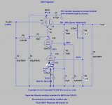
Pretty close, but the discussed filament changes should be made to V2 filament circuit. (the pass tube)
I recommend a 12AX7LPS or genuine 7025 for V1 error amplifier if AC filament power is to be used. For V1 I recommend a resistive divider set to about 140V to bias up the filament supply. A pair of 150K in series across the output with a ~0.47uF cap from the center connection to ground is what I would recommend. The filaments should be powered by separate windings.
I recommend a 12AX7LPS or genuine 7025 for V1 error amplifier if AC filament power is to be used. For V1 I recommend a resistive divider set to about 140V to bias up the filament supply. A pair of 150K in series across the output with a ~0.47uF cap from the center connection to ground is what I would recommend. The filaments should be powered by separate windings.
Pretty close, but the discussed filament changes should be made to V2 filament circuit. (the pass tube) OK understood
I recommend a 12AX7LPS or genuine 7025 for V1 error amplifier if AC filament power is to be used. For V1 I recommend a resistive divider set to about 140V to bias up the filament supply. I will use regulated DC
A pair of 150K in series across the output with a ~0.47uF cap from the center connection to ground is what I would recommend. The filaments should be powered by separate windings. Sorry my ignorance for V2 pins 3 & 4, V1B pin 7 or V1B pin 2?
6BQ5 filaments are: pins 4 and 5.. Connect pin 3 through 470K resistor to pin 4. Connect 0.47uF 400V capacitor from pin 4 to ground.
12AX7A filaments are pins 4/5 and 9 for 6.3V operation. Connect pin 4 and 5 to center of two 150K resistors connected across regulated output. Place 0.47uF 200V capacitor from pin 4/5 to ground. The dc filament supply must be floating - neither side connected to ground.
12AX7A filaments are pins 4/5 and 9 for 6.3V operation. Connect pin 4 and 5 to center of two 150K resistors connected across regulated output. Place 0.47uF 200V capacitor from pin 4/5 to ground. The dc filament supply must be floating - neither side connected to ground.
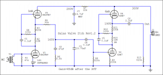
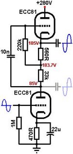
I will try first in a line preamp mu-follower with ECC81 280VDC 2.99mA per channel total circa 6mA, if I like the sound I will use also in the phono Salas Itch 300VDC 15mA. Attached pics with schematics.
Attachments
- Status
- This old topic is closed. If you want to reopen this topic, contact a moderator using the "Report Post" button.
- Home
- Amplifiers
- Tubes / Valves
- Perfect tube regulator