Yes that is exactly true, especially for low-gm tubes. However, for for high-gm types the 'optimum' becomes quite broad, so you can be quite relaxed about the exact operating current and still be fairly confident that the total noise will be almost as good as can be hoped for, and almost certainly better than any low-gm type you might otherwuise have used.
What evidence do you have to support this?
Cheers
Ian
What evidence do you have to support this?
Measurments (I showed you some of my results).
Also you can work it out just by looking at how quickly gm increases with current in small versus heavy-duty tubes.
Measurments (I showed you some of my results).
Also you can work it out just by looking at how quickly gm increases with current in small versus heavy-duty tubes.
Frankly I found those results difficult to believe and they are all at least half of what I measured myself with a professional test set.
Cheers
Ian
Frankly I found those results difficult to believe and they are all at least half of what I measured myself with a professional test set.
All my data were exactly consistent with other authors such as Harris 1947, Tharma 1963, Brophy 1961...
I suspect your higher results may be due to the weighting system used by your Lindos MS10, which I believe has a greater noise bandwidth than the 200-20kHz I used.
Also, the Lindos measures down to -70dBu or 244uV, which is not low enough to read the noise at the output of most triodes. You didn't mention an amplifier, so I'm not sure how you did this?)
Last edited:
What happens if one parallels several noise sources? I'm sure they would add up by some RMS mode. But lets say each time we increase the # of sources, we decrease the current in each, so the sum total current remains the same.
Wouldn't this amount to integrating the noise and thus reducing it?
If so, then a large high gm tube operated at relatively low current for its size would seem useful to reduce the noise. So maybe one should speak of current density integrated over large areas.
--------------
On the partition noise using a cascode off the g2, and combining that current with the plate, I would think that would be more effective than just the 20% increase in gm. Each current component contains the complement of the partition noise, and should cancel when combined. ???? This idea has been around for some time, but I haven't seen any measurements to confirm.
The g2 cascode should eliminate partition noise, which will help RF but not make much difference for audio. Measurements were in the Linear Audio article linked earlier in the thread, but as I said I doubt the measurement technique as it appears to show that pentodes are quieter than triodes.
Were the pentodes larger than the triodes maybe? (current density idea)
On the 1/f noise at interfaces, I'll offer a theory. (hand waving day here)
Suppose the local pathes across the interface become depleted in some way after current passes through them, so that the current pathes across the interface are continually changing route. This might be charge carrier depletion or thermal effects at point contacts. Perhaps quieter cathodes cold be formed if the emission coating were electroplated on (and then oxidised), rather than painted on and sintered.
In which case, the new technique for room temperature emitting cathodes, using plated on TiO2 would really be super.
Last edited:
Dave,
I’ve consulted Table 1 in Frank Blohbaum’s article in Linear Audio. It shows that for five of the twelve valves he measured, the circuit with the triode showed higher total input referred noise voltage than the pentode, though seven of the triodes were quieter than the same valve configured and measured as a pentode. Are these the results that lead you to conclude that the measurement technique is in doubt?
When I converted the input referred noise voltage to output noise voltages, all the pentodes (without exception) were noisier than the triodes by at least 3.4dB (in the case of the EF80) and as much as 14.0dB (in the case of the Russian 6∃6Π).
Regards,
Kim
I’ve consulted Table 1 in Frank Blohbaum’s article in Linear Audio. It shows that for five of the twelve valves he measured, the circuit with the triode showed higher total input referred noise voltage than the pentode, though seven of the triodes were quieter than the same valve configured and measured as a pentode. Are these the results that lead you to conclude that the measurement technique is in doubt?
I doubt the measurement technique as it appears to show that pentodes are quieter than triodes.
When I converted the input referred noise voltage to output noise voltages, all the pentodes (without exception) were noisier than the triodes by at least 3.4dB (in the case of the EF80) and as much as 14.0dB (in the case of the Russian 6∃6Π).
Regards,
Kim
I can't recall the details now, but that could be it. I suspected that his pentode noise measurements, being at a much higher anode impedance, were reduced by stray capacitance.
The equivalent noise resistance, Req, is the resistor at room temperature (or thereabouts) which if placed at the grid of a perfect noiseless valve would generate the same anode noise current into a short circuit as the real valve does. I suspect that by measuring anode noise voltage into a particular resistance he may be muddying the waters, but I would need to think a bit more about it. Shot noise and partition noise are essentially noise current sources, so to refer them to the input you need to divide by the transconductance - which is what the derivation of the 2.5/gm estimate does near the end of the calculation.
The equivalent noise resistance, Req, is the resistor at room temperature (or thereabouts) which if placed at the grid of a perfect noiseless valve would generate the same anode noise current into a short circuit as the real valve does. I suspect that by measuring anode noise voltage into a particular resistance he may be muddying the waters, but I would need to think a bit more about it. Shot noise and partition noise are essentially noise current sources, so to refer them to the input you need to divide by the transconductance - which is what the derivation of the 2.5/gm estimate does near the end of the calculation.
All my data were exactly consistent with other authors such as Harris 1947, Tharma 1963, Brophy 1961...
I suspect your higher results may be due to the weighting system used by your Lindos MS10, which I believe has a greater noise bandwidth than the 200-20kHz I used.
Also, the Lindos measures down to -70dBu or 244uV, which is not low enough to read the noise at the output of most triodes. You didn't mention an amplifier, so I'm not sure how you did this?)
Fortunately science is about truth and repeatability not consensus.
The Lindos measures in a 20KHz bandwidth to a published standard. It is certainly wider than your 200Hz to 20KHz with unspecified out of band response.
The Lindos can measure noise reliably down to below -90dBu or 25uV. It has its own bullt in 50dB amplifier for these measurements. The lowest noise from any tube circuit I have measured with is was a tad below -83dBu or about 55uV.
Cheers
Ian
What is this supposed to mean? You mistrust everyone's noise data?Fortunately science is about truth and repeatability not consensus.

What is this supposed to mean? You mistrust everyone's noise data?
When I mentioned Harris' work you said: "Unfortunately, Harris' statement was derived from measurements of only eight valves (1930s/40s types), so is a gross estimation for other types."
You then said: "All my data were exactly consistent with other authors such as Harris 1947, Tharma 1963, Brophy 1961..."
I mistrust someone implying someone else's data is unreliable and then quoting it in support of their own data.
Cheers
Ian
Harris' data is perfectly sound; it was his assumption that all valves would exhibit basically the same level of flicker noise, based on only eight, that was his gross estimation.
Yes, but the valves you are testing are other types so his work can in no way be a validation of your own.
Let's cut to the chase. You post the circuit of the ECC88 you used to get your measurements. I'll build it and see what results I get.
Cheers
Ian
Cherry and Hooper
Gents,
Thanks for contributions thus far, including suggesting Cherry and Hooper’s book, delivered today by the library. This evening’s reading included Chapter 3 which (among other things) summarises prior art in respect of noise in vacuum tubes. It draws on sources already noted (such as Schottkey, Bakker, North, Smullin and Haus) and others (Benham and Harris, Ziegler, T. B Tomlinson) for the classic equations for shot noise, partition noise and grid current noise. It’s clearly and succinctly written, with statements such as:
With the screen bypassed to the cathode, the expression for mean-square noise current generator for flicker noise at the anode can be simplified to:
where I is the anode current, c is a constant of ‘about two for most vacuum tubes’ and K 'for the anode must be determined experimentally.’ (page 79)
In Chapter 8, Cherry and Hooper apply this approach to an EF86 (pages 394 to 399). Making some reasonable assumptions, they confirm the manufacturer’s specified input equivalent noise voltage of approximately 2μV for the frequency range 25Hz to 10kHz (for a sample of 13 EF86s). In practice, this is analogous with (though not identical to) to Burkhard Vogel's estimation of a 1/f voltage noise correction factor (in Linear Audio Volume 4).
And by now, the irony meter is hitting 90 – Cherry and Hooper prefaced their work with the observation of one RW Johnson in 1961 that, while engineering and scientific gatherings sometimes featured good work:
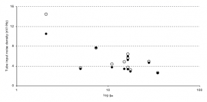
For interest, here is a scatterplot of equivalent input noise voltages for Frank Blohbaum’s sample of pentodes (on the Y axis) against the log of the datasheet gm. The open circles are for the pentode, the dark dots are for BestPentode. For this chart, I estimated output noise voltage from all other sources at 15μV to derive an estimate for the pentode alone. It would be better to have actual excess noise and gm for each measurement.
While the correlation is not sublime, the data indicate that noise falls for higher gm pentodes. The partition-noise estimates followed a similar pattern, as did the triode estimates.
Regards,
Kim
Gents,
Thanks for contributions thus far, including suggesting Cherry and Hooper’s book, delivered today by the library. This evening’s reading included Chapter 3 which (among other things) summarises prior art in respect of noise in vacuum tubes. It draws on sources already noted (such as Schottkey, Bakker, North, Smullin and Haus) and others (Benham and Harris, Ziegler, T. B Tomlinson) for the classic equations for shot noise, partition noise and grid current noise. It’s clearly and succinctly written, with statements such as:
For typical tubes … flicker noise exceeds shot noise at frequencies below a few kilohertz. Flicker noise in a given tube can only be reduced by reducing the anode current. (page 76)
If the screen is fed from a dc supply of finite internal impedence, a noise voltage is developed at the screen by the noise current. This noise voltage excites the screen-anode mutual conductance (gm/μs)vs and consequently increases the mean-square anode noise current. However, if the screen is connected by a low (ideally zero) impedence path to the cathode, no screen noise voltage can be developed … the practical conclusion is that the screen should be bypassed to the cathode with a capacitor (page 77)
Flicker noise is present on the cathode current stream of a pentode, and in addition is generated by the partition process. The partition component of flicker is relatively smaller than the partition component of shot noise. (page 78)
With the screen bypassed to the cathode, the expression for mean-square noise current generator for flicker noise at the anode can be simplified to:
d(i^2)=((K I^c)/f)df
where I is the anode current, c is a constant of ‘about two for most vacuum tubes’ and K 'for the anode must be determined experimentally.’ (page 79)
In Chapter 8, Cherry and Hooper apply this approach to an EF86 (pages 394 to 399). Making some reasonable assumptions, they confirm the manufacturer’s specified input equivalent noise voltage of approximately 2μV for the frequency range 25Hz to 10kHz (for a sample of 13 EF86s). In practice, this is analogous with (though not identical to) to Burkhard Vogel's estimation of a 1/f voltage noise correction factor (in Linear Audio Volume 4).
And by now, the irony meter is hitting 90 – Cherry and Hooper prefaced their work with the observation of one RW Johnson in 1961 that, while engineering and scientific gatherings sometimes featured good work:
too often the dissertation is a rediscovery of work already done (page v).
For interest, here is a scatterplot of equivalent input noise voltages for Frank Blohbaum’s sample of pentodes (on the Y axis) against the log of the datasheet gm. The open circles are for the pentode, the dark dots are for BestPentode. For this chart, I estimated output noise voltage from all other sources at 15μV to derive an estimate for the pentode alone. It would be better to have actual excess noise and gm for each measurement.
While the correlation is not sublime, the data indicate that noise falls for higher gm pentodes. The partition-noise estimates followed a similar pattern, as did the triode estimates.
Regards,
Kim
Attachments
Aldert van der Ziel distinguishes many different physical causes for flicker noise in his book "Noise", interface resistance between cathode metal and cathode coating is only one of them. Some flicker noise contributions were constant with the bias current (expressed as an equivalent input noise voltage PSD), others increased and there were even some that decreased...
New AES paper on noise in Flicker Noise thread
All,
There’s reference to a new paper on flicker noise in triodes in a Flicker Noise thread (http://www.diyaudio.com/forums/tube...nates-triode-noise-audio-aes.html#post3819795). The paper is by Merlin Blencowe and includes experimental DATA and is well worth the read.
All,
There’s reference to a new paper on flicker noise in triodes in a Flicker Noise thread (http://www.diyaudio.com/forums/tube...nates-triode-noise-audio-aes.html#post3819795). The paper is by Merlin Blencowe and includes experimental DATA and is well worth the read.
All,
There’s reference to a new paper on flicker noise in triodes in a Flicker Noise thread (http://www.diyaudio.com/forums/tube...nates-triode-noise-audio-aes.html#post3819795). The paper is by Merlin Blencowe and includes experimental DATA and is well worth the read.
An excellent paper which should be mandatory reading for all tube audio designers.
Cheers
Ian
- Home
- Amplifiers
- Tubes / Valves
- Pentode noise