Yeah, I didn't work of the silk screen since it doesn't show the holes, I worked of the details print I showed above. It doesn't list the pinout and I went by the symbol shown for the device. Not blaming anyone but myself for not looking further. If you noticed my edit, I have since researched the pinout of the device, something I obviously didn't do the first time. However, after changing around the devices it is still not working. I don't know why I am still fooling with it other than I has some time to kill while I'm waiting for parts. I should just toss it and wait for you to get some PCB's for your design. However, with as much trouble with oscillation as everyone seems to be having with it, maybe this isn't the amp for me.
Blessings, Terry
Blessings, Terry
Last edited:
There isn't much trouble with oscillations, if one follows either Shaan's schematic, or Lazy Cat's 1.4 schematic and BOM. (I have built both, and I also have LC's modules for comparison). If one wants to build with different components, or different supply voltage, or different input circuit, it is best to adjust everything accordingly....However, with as much trouble with oscillation as everyone seems to be having with it, maybe this isn't the amp for me...
When I blew up some transistors, it was because I wanted to see what would happen under certain conditions. So, it was not a fair test of a design, it was meant to make some tweaks.
This is completely different from having a bad result when you are trying to get something to work. What I did was the opposite. I already had a tested circuit which worked, and sounded right, before I changed things.
Component failure is a not a desirable consequence of this, but not unexpected. (even then it only happened because I let it oscillate too long, so you are in good company with donkeys ears...
 )
)As a result, the BOM I give to other people has compensation caps which are larger than typically posted here (47pF), I use larger Latfet gate resistors, as well as other component differences. I also did not design for the almost infinite bandwidth LC's modules are capable of (my results on that are posted in this thread). The rail caps on my boards are larger than what Shaan uses with BD139/140 (I use different VAS transistors and a higher supply voltage). I also use higher wattage 10R resistors in the front end filter now, and in the Zobel, etc. Those are also not required with Shaan's original schematic and supply voltage.
well I have other problems. I will have to dig into it at another time. something is causing it to swing to the positive rail. I even pulled the BC550/560 and tested them. they test fine. I would rather build your circuit.. please let me know when it available.
Hi Terry.
You're welcome to modify/build/share any/all of the designs in this thread. I am sure you will have a faultless setup with Pete's design. Will be happy to see your build of the pro layout.
In the meantime you may read post11 and post12 in page2 of this thread. The issue with my layout and the explanation is posted there.
Thank you for your patience.
Hi Shaan,
I didn't mean to imply that there was anything wrong with your design. I am sure it is in my etching job and/or soldering. I tried to be very careful but you saw how my etch job came out. Not the best. I don't want to keep giving bad reports when I know it is only that I a bad etch job to start with. My biggest issue is that I am just finishing up two other amps and am really strapped for time. I just think I will have better results if I build this amp on factory made boards. If those existed for your layout would be trying that.
Blessings, Terry
Yeah, I didn't work of the silk screen since it doesn't show the holes, I worked of the details print I showed above. It doesn't list the pinout and I went by the symbol shown for the device. Not blaming anyone but myself for not looking further. If you noticed my edit, I have since researched the pinout of the device, something I obviously didn't do the first time. However, after changing around the devices it is still not working. I don't know why I am still fooling with it other than I has some time to kill while I'm waiting for parts. I should just toss it and wait for you to get some PCB's for your design. However, with as much trouble with oscillation as everyone seems to be having with it, maybe this isn't the amp for me.
Blessings, Terry
My oscillations problem may be due the breadboard inductances and capacitances and/or may be due to the fact that I use different transistors in the front end AND and VAS. I did that so that I can run my board at +/- 55V once I shake all the bugs out.
With the input shorted, there are no oscillations and the output offset is incredibly small and stable.
I would suggest that you consider doing a point-to-point soldered board. You would spend less time than etching boards in my opinion. Or wait for PMI's boards to be available.
I spent about 2 hours initially wiring up the breadbaord. When I ripped it up for V2 with 0.1% resistors the re-wire was about 1 hour.
My ultimate suggestion for you is to spend some time creating a circuit that you can plug your transistors into to measure hfe/Beta at 30 to 35V Vce and at 2mA Ic for the front end parts and 10-15 mA Ic for the VAS parts. Transistor matching is important for a balanced circuit such as the VSSA. Most of my time with this project was spent buying and testing transistors for matched pairs.
...I would suggest that you consider doing a point-to-point soldered board. You would spend less time than etching boards in my opinion...
Why not. I too encourage P2P builds. For reference, attached below is my take on VSSA for the very first time, on veroboard. I think component placing has a big influence on stability, as this little ugly guy was stable since its birth while sonically resembling its genus, the
 SSA.
SSA. Attachments
Nothing ugly about your P2P implementation. I would be proud to perform work of this quality.Why not. I too encourage P2P builds. For reference, attached below is my take on VSSA for the very first time, on veroboard. I think component placing has a big influence on stability, as this little ugly guy was stable since its birth while sonically resembling its genus, the
Nothing ugly about your P2P implementation. I would be proud to perform work of this quality.
Shaan is definitely the master of that art.
...me tooNothing ugly about your P2P implementation. I would be proud to perform work of this quality.
Why not. I too encourage P2P builds. For reference, attached below is my take on VSSA for the very first time, on veroboard. I think component placing has a big influence on stability, as this little ugly guy was stable since its birth while sonically resembling its genus, the
Hi Shaan,
For the interconnection, are you utilizing the resistor lead, or using another appropriate wire size to connect the parts?
BTW, your veroboard looks great and pro!
Well I'm gaining on it. I have one side playing. I am noticing a couple things that are of some concern though I'm not sure if they are. First thing is the BD139/140 are running pretty hot. They are on the same heatsink but the 139 is about 135F and the 140 is 145F. I have the PSU set at +/-37Vdc. The outputs are sitting at 109F. Ambient temp is 80F. The bias is sitting at 150mA measured at the negative rail input. Offset is +79mV. I know I need to adjust that and will once I know everything else is OK.
How do these things look? I'd like to get this side set properly so I can use this one to trouble shoot the other.
Blessings, Terry
How do these things look? I'd like to get this side set properly so I can use this one to trouble shoot the other.
Blessings, Terry
Last edited:
You can measure the voltage across the 10Ω resistor in the emitter circuit of the VAS (the BD139 / BD140) transistors and calculate the VAS current. Ideally we are looking for ~12mA here; less current (down to ~6mA) runs them cooler and more current (up to 20mA) needs significant heat sinking.
Since your rails are on the upper end of the functional range (I regard 40V to be the max without really having to tweak values too much) you could increase the 15kΩ 'current injectors' to 18kΩ to bring both the current through the input transistors and VAS transistors down. Alternatively you could use 15Ω or 18Ω in the VAS emitter circuit to bring the current down if it proves to be a little high, though switching the 15kΩ for 18kΩ is likely the better overall solution, leaving the VAS emitters with the 10Ω resistors.
Trimming the offset is pretty easy. I used a 1MΩ potentiometer in parallel with one of the 15kΩ (or 18kΩ if substituted) to see if offset improved or worsened, put it where it improves the offset and gradually reduce the value of the pot until the offset is as low as you can reasonably get. Remove the pot and measure the resistance and install the closest standard value you can in parallel with the 15kΩ (or 18kΩ if substituted) you had the pot in parallel with.
Glad to hear you are making some progress.
Just when I thought it was safe to go back in the water............
Back to square one. I tried to very carefully take some measurements. Of course, on my last one, the probe slips and shorts the BD139 which takes out the four 10R, two 470R, the BD140 and the BC560. Great! I pull all the transistors go looking for matched sets. I do well on the BD139/140 but I'm not too close on the 550/560. I get as close as I can. I carefully install all the transistors, armed with my new knowledge of how the VAS transistors are oriented. I install all the resistors. I don't have any 15K or 18K so I stick 20K in there for now. I figure I'll watch it and see how it goes. I checked carefully for solder bridges, double checked all my resistors and checked for continuity at every new solder point. Hooked up the power supply to the variac and brought it up slowly while watching the DC on the output. Half volt, one volt, three volts, six volts, fifteen volts, full power, 35v offset. Shut it down. Nothing smoking but the input pair are very hot to the touch. I'm going to keep after this thing because I'm not going to let it whip me, but this is the last board I will work on that is this tight and doesn't have solder mask. I've had enough for today.
Blessings, Terry
Hello Terry.
I'm having the same problem with the boards I made, the current offset varies a lot and current VAS is very high (+ - 30mA), doing the BDs get too hot (Also observed that as the BDs get heated, the quiescent current rises along.). I am following the progress of your tests and I'm doing some tests too with resistors of different values, welding caps of 20pF between the base and collector to try to stabilize but also not so far achieved good results. If I get any positive result (or not), I'll post my experiences here in the forum. :/. Hugs.
I'm having the same problem with the boards I made, the current offset varies a lot and current VAS is very high (+ - 30mA), doing the BDs get too hot (Also observed that as the BDs get heated, the quiescent current rises along.). I am following the progress of your tests and I'm doing some tests too with resistors of different values, welding caps of 20pF between the base and collector to try to stabilize but also not so far achieved good results. If I get any positive result (or not), I'll post my experiences here in the forum. :/. Hugs.
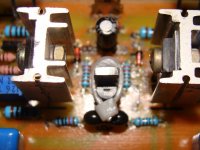
Are you gents gluing / heat shrinking the input transistors together? That's important for the DC conditions to be stable.
As mentioned in a prior post increasing the 15kΩ to whatever reasonable value brings the input and VAS currents under control may be needed if you are using supplies higher than ~35V.
There are also no other resistor values substituted? Some of them are interdependent, so a quick value substitution can result in needing to change others.
Compensation values of 20pF to about 47pF are about right if needed, but may not be required at all.
Hello, jkuetemann.
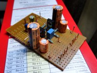
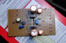
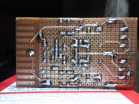
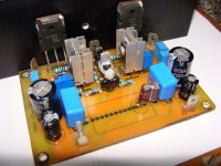
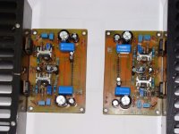
A while ago I posted the board that we made based on the Shaan's layout, but with minor changes (basically a extra polyester capacitor). Here are pictures of our board (shaan excuse us if the card does not fit the purpose of the topic, but we did tests without the polyester caps and the results were similar, and we are thinking of discarts it). We are in the fight to solve the problems and doing tests. Thank you for your attention. Hugs.
A while ago I posted the board that we made based on the Shaan's layout, but with minor changes (basically a extra polyester capacitor). Here are pictures of our board (shaan excuse us if the card does not fit the purpose of the topic, but we did tests without the polyester caps and the results were similar, and we are thinking of discarts it). We are in the fight to solve the problems and doing tests. Thank you for your attention. Hugs.
Attachments
Watch out the BD139-140
This is true, I just remember that I also has a problem with the BD139-140 too...
before I use the BD139-140 I check their the hFE with DMM, I use higher hFE around 200+ closely match hFE. I thought it good cos it higher hFE,
but I was wrong, got burn 4 pcs 10 ohm resistor because of that transistor.
Then I replace with another grade BD139-140 hFE around 150-160 & I still use it until today no bad thing happening again, just lot of good thing
I'm also add the compensation caps + zobel too (long & big speaker cable)
For all don't surrender yet, think the magic sound of this amp...
Now with adding a buffer, this amp really feel powerful
Some people hear it magic can't believe that I use only 50 watt amp.
I only use small transformer with 4 x 6800uF elco's
Depending on the producer of BD139/140 it may be even necessary to use compensation caps with them. Some BD139/140 transistors are prone to oscillation.
This is true, I just remember that I also has a problem with the BD139-140 too...
before I use the BD139-140 I check their the hFE with DMM, I use higher hFE around 200+ closely match hFE. I thought it good cos it higher hFE,
but I was wrong, got burn 4 pcs 10 ohm resistor because of that transistor.
Then I replace with another grade BD139-140 hFE around 150-160 & I still use it until today no bad thing happening again, just lot of good thing
I'm also add the compensation caps + zobel too (long & big speaker cable)
For all don't surrender yet, think the magic sound of this amp...
Now with adding a buffer, this amp really feel powerful
Some people hear it magic can't believe that I use only 50 watt amp.
I only use small transformer with 4 x 6800uF elco's
Here are pictures of our board.
Efragnani, those sinks between TO-92 parts.... I think they simply get things more difficult, since the goal is to thermocouple both devices, not to sink the heat they might produce. That's my 2 cents.
- Home
- Amplifiers
- Solid State
- PeeCeeBee