Greetings,
I'm considering getting a switch mode power supply for this amplifier, but I'm concerned about ripple-rejection.
I've found two suitable SMPS's from Connex Electronics.
I'm considering getting a switch mode power supply for this amplifier, but I'm concerned about ripple-rejection.
I've found two suitable SMPS's from Connex Electronics.
- One says "it is suitable for both class AB and class D/T amplifiers, which have average PSRR value." . . . whatever "average" is.
- Another says "This power supply is suitable for . . . amplifiers which have the PSRR greater or at least 57dB. "
First post: https://www.diyaudio.com/community/threads/peeceebee-v5-gb.395709/
Specifications:
Power (+/-50V PSU, 0.1% THD) - 140Watt into 8R, 250Watt into 4R
Frequency response (simulated) - ~2Hz to ~700KHz (-3dB)
Slew Rate - 60V/uS
Offset variation - +/-10mV
SNR - 112dB+
AC gain - x28 (28.9dB)
DC gain - Unity
Input level for 250W into 4R - 1.2VRMS (~3.4V P-P)
@shaan
Great amp. You really thought of everything when designing.
I have a question about big transistor mounting. Is it recommended to:
- bend the transistors flat against the board, then put the screw through both the PCB and the part? or
- Leave space between the transistor and the PCB, and only run the screw through the transistor. The screw head would be between the PCB and the transistor, and the screwdriver would go through hole in the PCB?
Just put an old bd139 or so between PCB and power transistor . This way you've your space and also a firm mounting .I have a question about big transistor mounting. Is it recommended to:
- bend the transistors flat against the board, then put the screw through both the PCB and the part? or
- Leave space between the transistor and the PCB, and only run the screw through the transistor. The screw head would be between the PCB and the transistor, and the screwdriver would go through hole in the PCB?

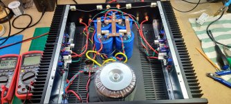
As promised. Here is my progress on the PeeCeeBee V5.


- Case is the Pesante 2U from Modushop by HiFi2000.
- The heatsinks will be flat against the back of the chassis, with a fan forcing outside air through the heatsink channels
- I'm using the SMPS300RE switching power supply from Connex Electronic.
- I also have the Subbu DAC, a group buy from 2013 Subbu DAC with an old Twisted Pear TORX unit, So the only input will be S/PDIF
Hi all,
Recd the V5 amp modules some time back... will start the build soon.

The heat sink... BTW planning to build mono blocks.

PSU modules: 4x15000 uf 100vdc... trafo will be 35-0-35 600va on each channel.


Proposed chassis: front view.

Rear view: yet to get them made.

...
Recd the V5 amp modules some time back... will start the build soon.
The heat sink... BTW planning to build mono blocks.
PSU modules: 4x15000 uf 100vdc... trafo will be 35-0-35 600va on each channel.
Proposed chassis: front view.
Rear view: yet to get them made.
...
- Home
- Group Buys
- PeeCeeBee V5 discussion thread