I fired it up tonight and the good news is that it didn´t blow up (or at least, so it seems). The bad news is that I am not completely satisfied with some voltages, so I need some help:
1. How stable should the 0V DC at R17 be? Mine fluctuates, somewhere in the range of -20mV to +30mV. It goes up, then down, then up again etc (mostly staying positive). Is this normal?
2. The voltages around Q3 are lower than they should be. I get 7V at the base and 6.4 at the emitter and collector. That's 3V less than other measurements I've seen. I remember vaguely someone else having this problem in this thread. Could it have something to do with the Idss of the quad Q6-Q9? (9,3 mA in my case). Voltages at the source of Q6-9 are 68mV. This is also somewhat higher than Wayne's figures (10-40mV) and measurements of someone else who got 53mV.
Other voltages are quite close. Maximum deviation 0,6V at the emitters of Q10 and Q11 (I've got -22.4 in stead of -23). But I've got + and - 23.5 V at the regulators in stead of + and - 24.
Hello,
As you have read further, I did away with lowering R10 and everything sounding fine. Although, I have addressed the same question about voltages to Wayne in PM, there were no replies.
Here's the Waynes values sheet: http://www.diyaudio.com/forums/attachments/pass-labs/290370d1341565509-pearl-two-pearl2votages.pdf
BTW I've got the same +-30mV drift as you've got and I consider it a safe one.
I very much admire you P2P build.
Thank you for your reply. I indeed read some more and I think PierreQuiRoule stated that the voltages around Q3 can differ with Idss of the quad. Higher Idss, lower voltages. That could explain the lower voltages with my quad (Idss around 9.3 mA). I'll start with replacing R10 with 6.81k, I've got some spare ones of those.
measured Q3 voltages:
with R10 = 10k:
Vc = 6.45 Vb = 7.07 Ve = 6.40
with R10 = 6k81:
Vc = 6.28 Vb = 6.87 Ve = 6.21
still not Vc > Vb > Ve
but with R10 = 4K75:
Vc = 6.32 Vb = 5.95 Ve = 5.31
Here Vc > Vb > Ve
Is this looking good in the eyes of the experts? Move on to building the left channel?
with R10 = 10k:
Vc = 6.45 Vb = 7.07 Ve = 6.40
with R10 = 6k81:
Vc = 6.28 Vb = 6.87 Ve = 6.21
still not Vc > Vb > Ve
but with R10 = 4K75:
Vc = 6.32 Vb = 5.95 Ve = 5.31
Here Vc > Vb > Ve
Is this looking good in the eyes of the experts? Move on to building the left channel?
Wellerman. - Catching up to you. Looks good.
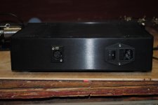
Finished my PSU done today. Had to sort hack the wiring between the rectifier boards, caps and and all the signal ground connections - I guess you cannot always have a nice PCB! Not pretty but safe and solid. I followed the PSU from the Pearl 2 article except added the missing signal ground between the 2 caps that 6L6 pointed out. Measured -31.6 and + 31.2 v on the output. All seems good. Drilled a small hole and glue gunned a blue led on the front panel with a 4.7k, 3 watt resistor for a power indicator. Ready to move on to the amp boards. My in-laws bought me a Hakko fx-880 soldering station - my wife emailed them my Amazon wish list. Thanks again to 6l6 for providing an great online build guide and plenty of offline help and advice.
Finished my PSU done today. Had to sort hack the wiring between the rectifier boards, caps and and all the signal ground connections - I guess you cannot always have a nice PCB! Not pretty but safe and solid. I followed the PSU from the Pearl 2 article except added the missing signal ground between the 2 caps that 6L6 pointed out. Measured -31.6 and + 31.2 v on the output. All seems good. Drilled a small hole and glue gunned a blue led on the front panel with a 4.7k, 3 watt resistor for a power indicator. Ready to move on to the amp boards. My in-laws bought me a Hakko fx-880 soldering station - my wife emailed them my Amazon wish list.
Thanks again to 6l6 for providing an great online build guide and plenty of offline help and advice.Attachments
OK, nice to see another Pearl II in the making. I will finish the left channel this week I hope. If that measures OK as well, I will then test both on an old amplifier and old speakers. If they pass that test, I will put them in their case and hope I will not have problems with hum.
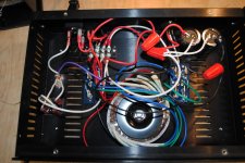
I finished the left channel today (shown on the right in this picture):
Voltages measure well, mostly within 0.1V from right channel voltages.
Voltages around Q3: Vc = 6.09, Vb = 5.95, Ve = 5.31. Vc is 0.2 lower than in the right channel, but I guess this is still OK.
I still need to isolate the voltage regulators from their cooling fins, and then later this week I can start testing them with some real music.... Oh yes, and trim the leads of those 4k75 R10's
An externally hosted image should be here but it was not working when we last tested it.
Voltages measure well, mostly within 0.1V from right channel voltages.
Voltages around Q3: Vc = 6.09, Vb = 5.95, Ve = 5.31. Vc is 0.2 lower than in the right channel, but I guess this is still OK.
I still need to isolate the voltage regulators from their cooling fins, and then later this week I can start testing them with some real music.... Oh yes, and trim the leads of those 4k75 R10's
Looking really good! What are you doing for the PSU?
Why bother? They don't touch anything, and this way they will have better thermal transfer to the heatsink.
I still need to isolate the voltage regulators from their cooling fins,
Why bother? They don't touch anything, and this way they will have better thermal transfer to the heatsink.
PSU is shown in post 1711. Just the one from the Pearl II article with 2 CL60 NTC's added. And a 2x24V toroid in stead of 2x22V.
I wanted to isolate the cooling fins to make the thing less vulnerable. Dropping something on the print now makes it easier to short something to ground. But maybe I will leave it like it is...
I wanted to isolate the cooling fins to make the thing less vulnerable. Dropping something on the print now makes it easier to short something to ground. But maybe I will leave it like it is...
I hooked up both channels (one at a time) to a Denon PMA880R connected to a small Eltax speaker (so I'd only blow up old stuff if something went wrong).
Both channels work, but there is something wrong with the left channel: it's very noisy. Way more noisy than the phono stage of the Denon (at it's MC setting). The right channel on the other hand is much better; a bit quieter than the Denon. Any suggestions what could be wrong in the left channel? Voltages measure OK, about the same as the right channel. Only thing is I'm not so sure about the 0V DC I'm supposed to measure at R17. It tends to drift a bit. Will have to analyse that some more.
I think I could do with a bit more gain, maybe 60dB. What is the preferred method here? Lowering the value of R14 (to something like 600 Ohm) or introducing R15? And which value for R15?
On a hunch I changed out Q2 and that did the trick. Now the left channel has low noise like the right channel. P1 needed to be adjusted quite a bit with the new Q2.
Now I am going to experiment a bit with more gain. I've got some resistors on order and will try out 750 Ohm for R14 first (gain 57,5 dB). If that is not enough I will go to about 60dB gain. Trade-off between gain and noise I guess.
Now I am going to experiment a bit with more gain. I've got some resistors on order and will try out 750 Ohm for R14 first (gain 57,5 dB). If that is not enough I will go to about 60dB gain. Trade-off between gain and noise I guess.
Which capacitor on the Pearl 2 board sets the capacitance loading for the cartridge?
Its C22, (100pF). You have to consider capacitance of the cable between cartridge and phono stage, minus that from required cartridge loading capacitance and arrive at proper value of C22.
You would probably hardly need C2 as many cables from the turntable will already have 100pF capacitance themselves. But MC cartridges are not so sensitive to capacitance as MM. For my Goldring Elite, capacitive loading is specified as 100-500pF, so I have just used 100pF for C2.
You would probably hardly need C2 as many cables from the turntable will already have 100pF capacitance themselves. But MC cartridges are not so sensitive to capacitance as MM. For my Goldring Elite, capacitive loading is specified as 100-500pF, so I have just used 100pF for C2.
I will be using the Ortofon M2 Blue cartridge. Recommended load capacitance is 150-300pF, so looks like the default 100pF will work fine.
Any suggestion as what kind of capacitor? Silver mica OK?
Thanks
100pF probably fine, you could order some 50pF as well to experiment with. I used silver mica. Some are enthousiastic about them, some less. But with only 2 silver mica's in the cicuit (C9 as well) I'm not really afraid they will give me a grainy sound. From what I've experienced so far my Pearl has a warm sound signature.
100pF probably fine, you could order some 50pF as well to experiment with. I used silver mica. Some are enthousiastic about them, some less. But with only 2 silver mica's in the cicuit (C9 as well) I'm not really afraid they will give me a grainy sound. From what I've experienced so far my Pearl has a warm sound signature.
Hmmm.... maybe I will setup a 2-gang rotary switch with a couple different values to experiment with the loading caps.
Have you ever compare the Pearl 2 with other phono stage? I am wondering where it stands sonically compared with $1000-ish commercial phono stage. I was originally going to build the ONO but it is a more complicated project.
Have you ever compare the Pearl 2 with other phono stage? I am wondering where it stands sonically compared with $1000-ish commercial phono stage.
Comparing the Pearl or Pearl2 with a $1000 phonostage it easy - it will beat them into submission, into a bloody pulp, to within an inch of their life. The Pearl really is that good. (assuming you build it well)
A 1000 buck phonostage, using the 4 to 1 cost to retail formula costs $250 to make. Half of that is labor, giving it about $125 worth of parts.
- Home
- Amplifiers
- Pass Labs
- Pearl Two