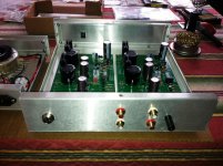
Ooh! Silver bumper Naim gear. Nice!
Are your cases reproductions or just something very similar?
Use 2 for the Pearl, PSU in one, both RIAA in the other.
Save the third for a linestage/selector.
Or, if you want to pursue another direction, sell the cases to me...")
Exact reproductions. He even uses the same paint.
I'd have to sand the edges to get the "silver bumpers" though, they come all-black.
I've got Naim stuff now, and while I'm sort of sick of that sound, I've always been fond of the package.
Have you got a favorite connector for outboard power supplies?
The connector is a 4-pin microphone plug from Radio Shack.
4-Pin Female CB and HAM Radio Microphone Plug : Microphone Plugs | RadioShack.com
4-Pin Panel Mount Microphone Audio Jack : Microphone Jacks | RadioShack.com
They can also be found in a 5-pin version
4-Pin Female CB and HAM Radio Microphone Plug : Microphone Plugs | RadioShack.com
4-Pin Panel Mount Microphone Audio Jack : Microphone Jacks | RadioShack.com
They can also be found in a 5-pin version
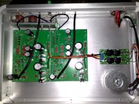
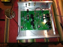
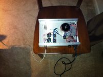
Thanks guys. Meanwhile I've got one board fired up and got going, I think its looking good so far.
Initial observation with bare board connected to DIY PSU (2X 22V 40VA transformer) dual 35VDC at output. Mains at 240V/50Hz.
1. Using ZVP3306A instead of 3310A (unobtainable from my side) ZVP3306 seems warmer on touch, normal?
2. C7 omitted.
3. C15 omitted.
4. Ordinary red LED from spares (unknown spec vF)
5. Voltage across R28/R29 is 1.12VDC. (intend to swap LED's to get closer to 1V) is closer to 1V better or leave it as is?
6. P1 adjustment looks good achieved at near zero volts.
7 Noticed it takes quite a while to go off (LED remains on for quite a while before it fades off) when powered down. I reckon this is because of large filter caps and slow discharge.
8. I read somewhere that its important and good practice to install all the transistors as lowest possible to the pcb, not exceeding 8mm to the top of transistor. Glad I did this, perhaps this is will help in performance.
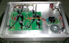
Finally got some 3mm 1.8vF red LED, managed to achieve 1.03V at R29 and 1.08V at R28.
I had to swap the lot to get closest to 1V. (considering my DVM is about 1% accuracy)
All other voltages are within or close to ballpark.
I intend to reduce the gain replacing R14 to 5Kohm at a later stage. I'm going to listen to this board with designed perimeters first, also to let it be on for many hours just to ensure all ok.
looking for advice on different gain per board
Hi not much of a writer but read alot. just built Pearl II with top grade parts.
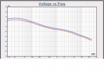
.1% res in the feedback and eq (100k\1k\6.8k\909) visay 1839 and polystyrene for eq caps. the front end seams fine both ch same gain at top of 6k8. But at the output 2db+ diff per channel. All resistor measure ok. don't know where the gain diff is coming from. offset is .05v, sounds is not quit right in low channel, but not bad bad so you could tell it is wrong. wave form looks ok on the scope. any thoughts
Hi not much of a writer but read alot. just built Pearl II with top grade parts.
.1% res in the feedback and eq (100k\1k\6.8k\909) visay 1839 and polystyrene for eq caps. the front end seams fine both ch same gain at top of 6k8. But at the output 2db+ diff per channel. All resistor measure ok. don't know where the gain diff is coming from. offset is .05v, sounds is not quit right in low channel, but not bad bad so you could tell it is wrong. wave form looks ok on the scope. any thoughts
Attachments
http://www.passdiy.com/pdf/PEARL 2.pdf
Page 3 : "The overall gain of the circuit as shown is 55 dB @ 1K Hz. Decreasing R14 from 1K to 300 Ohms gives 10 dB more gain when desired for lower output cartridges. R15 which normally would be shorted to 0 ohms can be replaced by a resistor to provide more gain as an alternative to reducing the value of R14. C15 has been placed on the board to allow for additional adjustment of equalization. In both cases these values are up to you."
Page 3 : "The overall gain of the circuit as shown is 55 dB @ 1K Hz. Decreasing R14 from 1K to 300 Ohms gives 10 dB more gain when desired for lower output cartridges. R15 which normally would be shorted to 0 ohms can be replaced by a resistor to provide more gain as an alternative to reducing the value of R14. C15 has been placed on the board to allow for additional adjustment of equalization. In both cases these values are up to you."
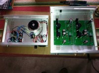
My Pearl II
Finished the Pearl II. I guess I'm having the same issue as other where there is an output inbalance. Right channel is louder than left channel.
All things being equal, is it the LED reference voltage that's not correct?
Is there a way to match the LEDs? Seen LED matching in another phono thread, but would like to know if the Pearl II LEDs require different type of matching.
Also, 60db gain is not enough for the Denon 103R. Has .25mV output.
Have to crank it past 3 o'clock on the BOZ-J volume.
Should I go for a SUT or can the Pearl II handle the low level by rising the gain further?
Thanks,
Vince
Attachments
Also, 60db gain is not enough for the Denon 103R. Has .25mV output.
Have to crank it past 3 o'clock on the BOZ-J volume.
Should I go for a SUT or can the Pearl II handle the low level by rising the gain further?
Apart from the position of the volume knob, how is the noise when you get things to a satisfying level?
Measure the voltage across the LED, see if it's different. Although it has little to do with gain as far as I can tell...
If you are dying to have an adjustment to get your outputs even, make R15 a multi-turn variable reistor and tweak it there.
I was going to ask the same thing. Do you not have enough system gain with your pre turned all the way up?
If you are dying to have an adjustment to get your outputs even, make R15 a multi-turn variable reistor and tweak it there.
Apart from the position of the volume knob, how is the noise when you get things to a satisfying level?
I was going to ask the same thing. Do you not have enough system gain with your pre turned all the way up?
Also, 60db gain is not enough for the Denon 103R. Has .25mV output.
Have to crank it past 3 o'clock on the BOZ-J volume.
Should I go for a SUT or can the Pearl II handle the low level by rising the gain further?
Thanks,
Vince
Vince, I put step-ups in front of mine, after trying the resistor tricks. Very happy with it.
Vince, I put step-ups in front of mine, after trying the resistor tricks. Very happy with it.
Tea-bag,
I placed a switch on the front to switch between 55 and 65 db.
Was thinking of using a SUT that brings up the gain 2x or 3x, instead of the usual 10x.
This way I can continue to use the MC levels instead of the MM levels.
Any thoughts on this?
If its not the LED causing the imbalance, what else could it be?
PS. On a hunch I went back to listen again. The imbalance has to do with switching between 56 and 65 db.
I cracked the volume using the 56 db setting and its fine. The imbalance happens when its switched to the 65 db setting. The resistors must not be matched somehow, although I checked them before installing them.
That's a relief!
Last edited:
- Home
- Amplifiers
- Pass Labs
- Pearl Two