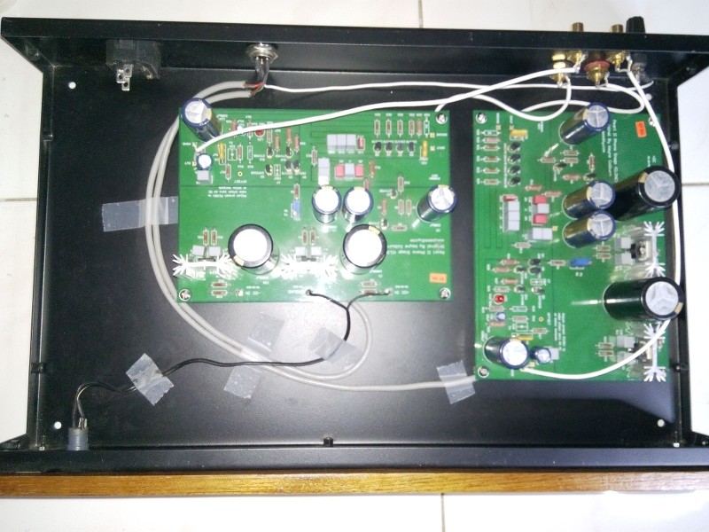
@Salas: Ok, so it should be exactly 10.1 V and 9.4 V - according to the plan, right? What about Q1 - ist that not so critical?
What about the JFETs? Might they have to do with the clipping as well?
Thanks and best regards
Michael
Q1 is at a capacitance multiplier filter. Should show one Vbe drop across. I.e. 0.6-0.7V
Q3 is the cascode transistor for the JFETs array. It has to have less Vbe than Vce to be in the active mode. It does by 0.1V only. (Vce=10.1-9.4=0.7V Vbe=10-9.4=0.6V). I am not sure of what is intended but I would prefer to see a few Volt across it instead.
The JFETs should be GR selection so not to draw much total current and not force higher drop than intended across R9. In such a manner they could choke the system.
Thanks a lot guys, that did it!
I replaced Q2 with a new one and removed C7 completelly - voila, the Pearl 2 sounds nice, warm and crystal-clear now - without any oscillations or distortions!
Also the voltage adjustment to 0V at the test-pad works better now.
I am so glad, it's not the JFETs, since those are the matched ones that came with the PCBs from Pass Labs...
Thanks for your experience and support!
Best regards
Michael
problem on neg psu R30 is fried
hi boys,
Is there a reference in this thread to a PSU problem where R30 on the Neg side gets fried, cuz that what happened to day
I took out the 7924 regulator and all was well..no frying of A NEWLEY FITTED R30 ..so C26 AND C25 are not shorting to deck..it.looked like the regulator was shorting R30 to earth? however on replacing the suspect regulator with a new one.. the same this happens......R30 fry's.... I checked for bad solder bridges on the regulator legs but the joints are fine, no shorts on the PCB.
Cold DC checks on the board show nothing obvious.. but .I cant find the original reference on the forums-- but I know 6L6 had a hand in solving it, its got to be fundamental but I cant see it?
cheers
Johnny ( in a two steps forward - one step backward frame of mind)
Maybe check for pin layout. My 7924 is gnd in out (seen from front, left to right), while the 7824 is in gnd out. If this is universal and you use the store boards this should be no problem (I however used perfboard for my Pearl).
Also check polarity of C26 to be certain, + should be on gnd, - to the input from the PSU.
That's all I can think of right now...
Also check polarity of C26 to be certain, + should be on gnd, - to the input from the PSU.
That's all I can think of right now...
thanks
Hi Wellerman, thanks for the reply
The regulator can only go I one way (as long as you put in the right way round!)--C 26 is orientated correctly (I will check the + to earth continuity again though) also..i will have another look tomorrow any further suggestions welcome sir.
regards
Johnny
Hi Wellerman, thanks for the reply
The regulator can only go I one way (as long as you put in the right way round!)--C 26 is orientated correctly (I will check the + to earth continuity again though) also..i will have another look tomorrow any further suggestions welcome sir.
regards
Johnny
power issue solved
Hi y ALL, just for the record , I found removing C 24 stopped R30 frying and restored the negative voltage to - 24.1 volts no issues.
I took the sensible approach and built the PSU sides first. Including C24 on the Neg side, cold tests showed C24 behaves like a normal capacitor (you can see it charging up when on the ohm's/continuity function on the DVM)
The PCB has no shorts I can detect or see (cleaned it all with IPA alcohol as a precaution anyway) SNIFF SNIFF
anyone had this issue??
cheers
JOHNNY
got that
hi boys,
Thanks Wellerman, all is well in terms of C24-- polarity correct etc , I have replaced the regulator, but will attempt to get a "name make" as it were , thanks itsmee--it seem all OK (for now!)
let ya know what happens when i power it all up (still anteing for a few "bits" to arrive!
regards
Johny
Problem with R30
Dear Johnny,
I think I know what is happening with your R30...
Being the 7915 a non-isolated specimem, the heatsink also become the "Input"
terminal of the regulator...
The only isolation between PCB ground plane and heatsink is the green mask.
When you touch the heatsink to change the IC or when you remove C24,
what happened is that some point of heatsink which was shortened to ground plane, suddenly become isolated.
Give a little spacing between both and your problem is definitely solved.
Regards,
Marcos
think you correct marcos
hi Marcos,
yes, I was think a similar thought(s) so I gave the heatsink(s) a "haircut" now they float in the air as it were with a nice little (air!) gap between the board and the heat sink, there has been no issues since.
(but I changed the -24v regulator as a precaution)
I have not powered it up yet though (waiting on some nice caps for the RIAA bit)
Thanks for you input sir, most helpful
regards
Johnny
hi Marcos,
yes, I was think a similar thought(s) so I gave the heatsink(s) a "haircut" now they float in the air as it were with a nice little (air!) gap between the board and the heat sink, there has been no issues since.
(but I changed the -24v regulator as a precaution)
I have not powered it up yet though
Thanks for you input sir, most helpful
regards
Johnny
If you can't adjust all the high voltage away with the pot, and you probably won't be able to, replace the ZVP3310.
Be extremely careful in handling, they are very static sensitive and easy to zap. It's not unusual at all to have killed one in construction, about half of the people building the Pearl 2 have done so.
Be extremely careful in handling, they are very static sensitive and easy to zap. It's not unusual at all to have killed one in construction, about half of the people building the Pearl 2 have done so.
- Home
- Amplifiers
- Pass Labs
- Pearl Two


