Promitheus,
I've been trying to get some info on the 2sc1844. I couldn't find the datasheet in Nec's website nor in google. It is is a very low noise transistor (0.5 nV/Hz^0.5) and seems very hard to find.
The question is why would Wayne change to ztx450 for all the stages when designing the Pearl.
I found the info below in this link
2SC1844 NPN Silicon Epitaxial Transistor,
AF Low Noise Amplifier
Bottom View:
_______
| E C B |
\_____/
Absolute Maximum Ratings :
Vcbo = 60 V
Vceo = 60 V
Vebo = 5 V
Ic = 100 mA
Ib = 20 mA
Ptot = 500 mW
Tj = 125 grdC.
Tstg = -55 to 125 grdC.
Characteristics at 25 grdC.:
DC Current Gain hFE at Vce = 6 V :
at Ic=0.1mA: min 150, typ 370
at Ic=1 mA : min 200, typ 400, max 800
Classification: P :200...400, F: 300...600, E: 400...800
Vbe at Vce=6V, Ic=1mA : min 0.55V, typ 0.59V, max 0.65V
Vce(sat) at Ic=100mA, Ib=10mA : typ 0.13V, max 0.3 V
fT at Vce=6V, Ie=-1mA : min 50 MHz, typ 100 MHz
Cob at Vcb=10V, Ie=0, f=1MHz : typ 4.8 pF, max 8 pF
Noise Voltage at Ie=-1mA, R(base to Gnd)=100kOhm,
R(emitter to Gnd)=1 kOhm, Rcoll=RLoad=10 kOhm,
f=10Hz to 1 kHz : typ 30 mV, max 45 mV
From the diagram typ Gain Bandwidth Product vs. Ie :
fTmax = 500 MHz at Ie=-40mA
From the diagram Noise Figure vs. Rg and Ic at Vce=6V,
f=1 kHz,..?(very small diagram, I need a microscope):
Area for NF better than 0.5 dB:
0.01mA/12 to 300 kOhm
0.1mA/1.4 to 30 kOhm
1 mA/260 Ohm to 3 kOhm
3.5mA/500 Ohm(highest Ie for this area)
The typ. DC Current Gain is very flat for 0.01...100 mA:
between 330 and 420.
")
Hi Promitheus;
RE: input Z: I meant to keep the existing 100K input Z not increase it to 1 Meg or 10 Meg (a bad idea). My post was meant to point out that Zin of the second stage dropped to 1K when the gain reduction jumper was installed.
As to who designed it, its kind of irrelevant, I imagine even Wayne Colburn occasionally updates or improves his own designs. I just noticed that the way it was done was strange. If the circuit sounds as good as you think, some characteristic(s) will undergo a significant change as the gain jumpers are added and removed.
I also stand by my statement that a controlled corner frequency that doesn't change with gain setting is the better choice.
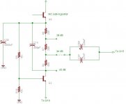
I've attached a partial schematic of the solution I had in mind. This has not been built or simulated but illustrates the idea. It is straightforward and should work OK.
With this technique several gain choices are easy to implemet and doesn't change the load on C37.
With this technique several gain choices are easy to implemet and doesn't change the load on C37.
Attachments
I think that's it's both safe and a good idea.
To remove turntable warp signals and tone arm resonance most people use a 4 to 6 Hz corner frequency. Opinions may differ, (I've seen 2 to 11 Hz for example).
So if the input Z to the next stage is about 11K (R51 + R80 + R41 plus a Q15 collector source Z of guessing 1.65K) then a 2.78 uF would have a 3 dB corner of 5 Hz. So either a 2.7 or 3.3 uF should be about right.
Since the original design used 220uF it probably makes sense to err on the large side maybe even a 4.7uF. The Z of the gain setting stack is so low that it has little effect of the capacitor size choice.
Still a good quality 4.7 uF film capacitor is physically large and will set you back anywhere from $1 to $100 each! (Is this a great hobby or what?)
C19 should probably stay much larger than C37. Since it provides negative feedback, too small a C will increase the gain below the corner frequency so probably 5 to 10 times C37 is a good idea. It can be a lower quality but I can't really say if an electrolytic is good enough. If the original desgn was known for good sound then an electrolytic is probably OK in this spot.
That's hard to answer. Where I put 40 dB on my partial schematic it was from the original schematic stated gain. For that tap, no values were different so the gain should be the same. If you leave out Q15 then the 40 dB number is wrong and you are right it should be somewhere around 34-35 dB.
The other issue is the output Z will be different, probably not an issue but a close look is warranted.
Fewer stages are almost always a good idea, but what if you buy another cartridge someday that needs the additional gain? Also different readers here may have different needs and when the time comes to debug the group build, it's helpful if most readers have the same circuit.
Still, this is a DIY forum, you can do whatever pleases you and changing other peoples designs is an excellent way to learn.
If I'm not wrong, the gain of the first stage (Q10, Q11, Q12, Q13 fets and the cascode Q14) is the following:
4 * (R66+R40)/(Rs + 1/gm)
where 4 is the number of fets, Rs is the resistance at the source (22R) and gm the transconductance of the fet (22 ms). The gain is then
4* (499+499)/(22+45,45)=59,58 which is about 35dB
Then we have negative gain with R41,R80 and R49, and then Q15 increases again the gain.
I don't think nobody will require more than 30dB. This is the reason I don't see the need of Q15 and additional caps unless there is something I'm missing.
You are right promitheus, the resistors only attenuate about -0,4dB and Q15 is only a buffer. The only purpose I see for this buffer is to invert the phase (that was already inverted at the previous stage).
Correct me if I'm wrong, but I believe the gain of Q15 should be (R41+R80)/R61 = 0,81 this means -1,81 dB
So the overal gain of the MC Ono stage is about 33dB
Correct me if I'm wrong, but I believe the gain of Q15 should be (R41+R80)/R61 = 0,81 this means -1,81 dB
So the overal gain of the MC Ono stage is about 33dB
Promitheus,
You can see the details on the figures in posts #174 and #176.
However, the figures for the Q10, Q11,Q 12, Q13 and Q14 gain depend on the transconductance of the fets. I assumed 22mS as was used for the Pearl since we were talking about the 2SK170BL (and not the GR version). Transconductance depends on IDSS and other factors, so I made some assumptions. The Ono is using the 2SK170GR and has a different IDSS.
BTW, according to the service manual (see page 4):
Gain 40 dB @ 1 KHz (MM)
71 dB @ 1 KHz (MC)
76 dB @ 1 KHz (MC)
Both have 2SK170 BL.
Or am I wrong?
I thought I read it somewhere in the forum, but I couldn't find it. The service manual doesn't specify.
I'm sorry, I shouldn't put that statement
- Status
- This old topic is closed. If you want to reopen this topic, contact a moderator using the "Report Post" button.
- Home
- Group Buys
- Pearl phono PCBs Group Buy