I have some news.
I changed the layout again.
I am not quite finished but the Board will be even smaller.
105mm x 63mm.
That means the board can be mounted lower and nearer to the Pearl Board and not on top of the MKP output Cap.
The PCB will be mounted on the Pearl with 3 plastik distance holders of 15mm which will be glued on the Pearl PCB.
I will show some picture how this works.
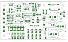
This is what it will look like in real size.
If you will use the board separately you can mount it using the 4 corners.
If you want to mount on top of the Pearl you have to use the 5th hole on top beside the 150nF Cap.
This must be done because the top right corner is directly above the Q4 ZTX450 transistor of the Pearl Board.
If you will use the board separately you can mount it using the 4 corners.
If you want to mount on top of the Pearl you have to use the 5th hole on top beside the 150nF Cap.
This must be done because the top right corner is directly above the Q4 ZTX450 transistor of the Pearl Board.
Attachments
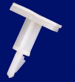
For the 3 corners on top of the Pearl I was thinking of something like this.
You can stick these to the Pearl board.
They have a sticker on the bottom side.
For the bottom left corner which is at the same position with the Pearl screw there are many way to do this.
The easiest is to use a long screw and fix the board with 2 nuts.
You can stick these to the Pearl board.
They have a sticker on the bottom side.
For the bottom left corner which is at the same position with the Pearl screw there are many way to do this.
The easiest is to use a long screw and fix the board with 2 nuts.
Attachments

")
Progress
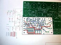
So I am doing some progress.
Just got the MC Pre PCBs.
If you want a high Resolution photo download here.
its big 1,5MB
http://www.audioconnexion.de/mconpearl.jpg
the stand offs must be trimmed but I think it looks good.
The total height is 5cm.
So I am doing some progress.
Just got the MC Pre PCBs.
If you want a high Resolution photo download here.
its big 1,5MB
http://www.audioconnexion.de/mconpearl.jpg
the stand offs must be trimmed but I think it looks good.
The total height is 5cm.
Attachments
So all the orders are ready.
It took a little longer then I thought.
I sent some ackages on Friday and the rest will be sent on Monday and Tuesday.
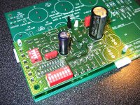
A small detail that you have to be carefull of on the board is transistor Q5.
The board was designed using BC550C transistors because at the time I couldn´t find the original 2sc1844.
I left the option open for both.
I did at the end find the low noise 2sc1844 so it has to be solder 1 pin shifted like in the photo I have attached.
The Pins of the bc550 are CBE and the 2sc1844 are ECB.
You can also see Q6. Some people have asked me which side is the round one.
Also be carefull of the resistors which have to be placed verticaly to save space.
For some reason R18 and R19 did not get printed correctly but at least you can see where they are.
The last correct layout is in POST #23
It took a little longer then I thought.
I sent some ackages on Friday and the rest will be sent on Monday and Tuesday.
A small detail that you have to be carefull of on the board is transistor Q5.
The board was designed using BC550C transistors because at the time I couldn´t find the original 2sc1844.
I left the option open for both.
I did at the end find the low noise 2sc1844 so it has to be solder 1 pin shifted like in the photo I have attached.
The Pins of the bc550 are CBE and the 2sc1844 are ECB.
You can also see Q6. Some people have asked me which side is the round one.
Also be carefull of the resistors which have to be placed verticaly to save space.
For some reason R18 and R19 did not get printed correctly but at least you can see where they are.
The last correct layout is in POST #23
Attachments
Also there are 2 points on the board called Star1 and Star.
These 2 points need to be connected with a piece of wire.
This connects Audio Star Ground with ground plane.
MC input should be connected to +MC and -MC
MM input should be connected to +MM and -MM
+Out and - Out should be connected to Pearl Input.
These 2 points need to be connected with a piece of wire.
This connects Audio Star Ground with ground plane.
MC input should be connected to +MC and -MC
MM input should be connected to +MM and -MM
+Out and - Out should be connected to Pearl Input.
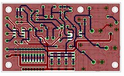
the meshed ground plane has a few advantages over solid plane.
1. lower stray capacitance
2. pcb remains flat
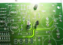
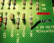
to power the MCpre board you need to take 29Volts of the Pearl board.
if you look at the picture attached you can see where this is.
on the right side of the board you see an arrow which points to R8 10Ohm, this is the ouput of the regulation circuit which feeds the Pearl.
You can take ground from the resistor R11 10K directly there.
just solder the cable on top.
+29Volts marked red goes to +V on the MCPre PCB
0V marked black goes to GND on MCPre PCB.
1. lower stray capacitance
2. pcb remains flat
to power the MCpre board you need to take 29Volts of the Pearl board.
if you look at the picture attached you can see where this is.
on the right side of the board you see an arrow which points to R8 10Ohm, this is the ouput of the regulation circuit which feeds the Pearl.
You can take ground from the resistor R11 10K directly there.
just solder the cable on top.
+29Volts marked red goes to +V on the MCPre PCB
0V marked black goes to GND on MCPre PCB.
Attachments
- Status
- This old topic is closed. If you want to reopen this topic, contact a moderator using the "Report Post" button.
- Home
- Amplifiers
- Pass Labs
- Pearl MC Pre-Preamp