steenoe said:He-he, yourselfHey Choky, I have to tell you this little secret: I am nearly done with the babblefish
Steen
regarding secret.........mebbe I have few really minor changes in Babel.....change all 0R22 to 0R33......for start you can use 4U7 in feedback path,later you can try without.......that's all from top of my head
if you are interested in good spk protection (universal type
 ) just mail me
cviller-sorry for off topic.........when I meet steen or babowana........it's usually mess........

I had a feeling that the 0,22 was a bit on the rough side Hey you should see my chassis for the Babbelfish its way cool in the oldfashion Aleph style I will take a shot tomorrow
My intention was to parralel 2 fets!! I will get back to ya in the Babbelfish thread!
Steen
Sorry, Cviller for this slight disturbance!!
Hey you should see my chassis for the Babbelfish its way cool in the oldfashion Aleph style I will take a shot tomorrow My intention was to parralel 2 fets!! I will get back to ya in the Babbelfish thread!
Steen
Sorry, Cviller for this slight disturbance!!
steenoe said:
Sorry, Cviller for this slight disturbance!!
No problem.
There is a small error in the posted layout R3 should have been a 2W resistor. I have corrected that and I think it should be ready for testing. So if anyone wants the copperside, just drop me an email. The layout is designed for primitive etching, so pads are all nice and large.
(The pdf on my web page is corrected)
http://viller.org/audio/pearlpcb.pdf
I changed the layout so that 2sk389 can be used. It is not too difficult to mount two 2sk170 in the footprint of a 2sk389 - harder the other way around!
I have also etched the board. Too bad the developer must have been old or something, because I usually get better results. I think the boards will work anyways.
Here is a picture of one of the boards:
You can see that I had to scratch some shorts.
I have also etched the board. Too bad the developer must have been old or something, because I usually get better results. I think the boards will work anyways.
Here is a picture of one of the boards:
An externally hosted image should be here but it was not working when we last tested it.
You can see that I had to scratch some shorts.

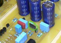
Couldn't wait any longer...
I hope it is not a smoker!
I'm a bit concerned about those big capacitors and ~45 vdc - should I do something before I turn on the voltage?
An externally hosted image should be here but it was not working when we last tested it.
I hope it is not a smoker!
I'm a bit concerned about those big capacitors and ~45 vdc - should I do something before I turn on the voltage?
cviller said:Couldn't wait any longer...
......................................
ugly!

The pmos Q1 in the psu was connected wrong - no smoke, but wrong voltages. I changed it and now it seems to be fine. I'll change it in the layout, if anyone want's to try to make their own board.
I have attached the schematics with the pmos flipped.
Now I just have to figure out how to test it without a turntable...
Attachments
Hi cviller, those populated boards look great. Happy to hear that the thing didnt explode A few bug's are to be expected.
If you measure the approx. same voltages at the points where Wayne put them in the schematic, you have all chances that the circuit works Please let us know how close your measurements are. The values probably wont be "bang on", but that is not of concern. As long as they are fairly close to Wayne's values, you should be fine.
Steen
A few bug's are to be expected. If you measure the approx. same voltages at the points where Wayne put them in the schematic, you have all chances that the circuit works
Please let us know how close your measurements are. The values probably wont be "bang on", but that is not of concern. As long as they are fairly close to Wayne's values, you should be fine.Steen
Not all of them are within 5%, but some of the values are fairly close. I have tested all the points and written them on the schem.
W is for wayne
R and L are the two channels... guess most people in here would figure that out anyways.
The only voltages that are really off are the small ones across R25 and R28-31 - but I guess it doesn't matter too much.
W is for wayne
R and L are the two channels... guess most people in here would figure that out anyways.
The only voltages that are really off are the small ones across R25 and R28-31 - but I guess it doesn't matter too much.
Attachments
steenoe said:That ought to work
Steen
I don't think that would do anything besides bringing the values closer to each others. The difference measured by Wayne is actually a greater than my measurements. His variation is 40% from a mean of 50mV and I have 12% of a mean of 121mV on the worst (R). Correct me if I'm wrong.
My higher voltages might be due to some noise, because I haven't connected the inputs to anything. If I hook up the system to my stereo, there is some noise when the inputs are not connected to something and this might generate a larger current across R28-31...
By the way you said that you would use some different capacitors - I can adjust the layout if you send me a list of those that does not fit and what the spacing should be instead.
Are the optional input capacitors (C14,16,17 on my schem) necessary for an MM pickup? Do I need to read its specifications and insert values accordingly, or can I just hear if there is something wrong?
Neither do iI don't think that would do anything besides bringing the values closer to each others.
Wow thanks, thats mighty kind of you. Maybe a set of different hole spacings for each capacitor would be nice. I will do a little measuring when I get home.I can adjust the layout if you send me a list of those that does not fit and what the spacing should be instead.
Not necessarily.Are the optional input capacitors (C14,16,17 on my schem) necessary for an MM pickup?
It depends on the cartridge. The cartridge's spec-sheet will tell you.
Steen
steenoe said:Neither do i
Wow thanks, thats mighty kind of you. Maybe a set of different hole spacings for each capacitor would be nice. I will do a little measuring when I get home.
No problem. The manuals are great too.
Attachments
IndeedThe manuals are great too.
Legspacings of 7,5 mm and 12 mm, besides those you used allready would be great.
Steen
steenoe said:Indeed
Legspacings of 7,5 mm and 12 mm, besides those you used allready would be great.
Steen
All capacitors except lyts and output cap have been changed to a version with 5,7.5,10,12 and 15 mm leg spacing. You can see the layout here:
http://viller.org/audio/2006nov_pearl/pearlpcb.pdf
I'll send you a pdf with copperside.
If anyone else want to do some etching I'll be happy to send pdf/ps with copperside in A4 or letter.
Too bad I have to wait until tomorrow to hear it...

Thanks a lot. The layout looks great. Time to experiment with different caps in the RIAA eq.I'll send you a pdf with copperside.
Steen
Finally got an opportunity to test my boards and I am astonished by how good it sound!!! 
The guy I made it for has a Marantz PM-15S1 amp with phono input and a SA-15S1 cd player. Before I made the pearl, we compared some records where he had both CD and vinyl and the vinyl version was ok, but very dull compared to the CD. After pearl, the situation is quite the opposite - first time for me to hear old records sounding better than CD's!
Thanks Wayne and Nelson!!!
cviller said:
All capacitors except lyts and output cap have been changed to a version with 5,7.5,10,12 and 15 mm leg spacing. You can see the layout here:
http://viller.org/audio/2006nov_pearl/pearlpcb.pdf
I'll send you a pdf with copperside.
If anyone else want to do some etching I'll be happy to send pdf/ps with copperside in A4 or letter.
Too bad I have to wait until tomorrow to hear it...
if you insist............
sasica5ATgmail.com
- Status
- This old topic is closed. If you want to reopen this topic, contact a moderator using the "Report Post" button.
- Home
- Amplifiers
- Pass Labs
- Pearl layout - how to organise things to avoid noise