Hi,
I am buiding the pearl 3 and it doesn't start very well: on the power supply, I have only D4 that lights up (not D3 nor D5...). I checked them with a battery and not only they light up, but the are soldered correctly...
Moreover, I have +/- 24.4 V on the outs (where i should have 20 V) and no continuity between the "chassis" hole on the board and the ground outputs... I have continuity between the "chassis hole" and the ground on the PCB (left empty) , and on every srews...
what did i do wrong ?
Hello
Not much help I know .. but there must be a mistake in your construction or component values .. as normally these circuits are very well tested
The only thing I do not like from a PCB design (this is constructive feedback) is their use of tiny solder pads that should be bigger and the use of surface mount components
some times (not always) PCB designers are not builders/constructors
How are you getting +/-24 volts from a transformer with 15 volt secondaries?
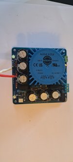
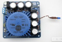
Also, in the first picture, I see several resistors that the top side pad has no solder...to me that says incomplete solder job, like the joint wasn't clean, or the temperature wasn't set high enough, or the iron wasn't held to the joint long enough. I'd re-solder all joints paying attention to how well it fills the hole.
Beyond that, there isn't enough info to help you any more than that...can you post the schematic without violating any copyrights?
Mike

Look i intentionnaly did not use exess soldering, like on both side... BUT flux has been use for each and all of them and the whole PCB was cleaned with isopropylic alcool three or four times...
shematics at step 40 there https://guides.diyaudio.com/Guide/Pearl+3/28
sorry i cannot copy past it... it must be protected...
thing is i cannot order the PCB by itself, nor with the kit at 150 dollars, cause it s out of stock so i am a little bit in the s...
shematics at step 40 there https://guides.diyaudio.com/Guide/Pearl+3/28
sorry i cannot copy past it... it must be protected...
thing is i cannot order the PCB by itself, nor with the kit at 150 dollars, cause it s out of stock so i am a little bit in the s...
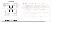
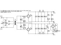
Sorry, yes you are right that s a good question.. though the transfo is bought after the BOM, it is positioned as indicated on the guide... the jumper for 240 V operation is correctly placed... here is a picture from the guide and the schematics from the manufacturer...
Attachments
The output voltages V+ and V- are high because the power supply is not loaded. Once attached to the Pearl 3 board, the voltage should drop.
Your voltage measurements across the LED voltage dropping resistors R9 and R10 indicate that their LEDs were not dropping any voltage, which is a sign that they are shorted (damaged). So that is probably the reason they do not light up. The voltage across R11 at 22.08V indicates that the attached LED was dropping approximately 2.4V, so that LED should be lit. The PS schematic shows R11 associated with D5. You have written that D4 was lit, and D5 was not, so that is strange.
Your voltage measurements across the LED voltage dropping resistors R9 and R10 indicate that their LEDs were not dropping any voltage, which is a sign that they are shorted (damaged). So that is probably the reason they do not light up. The voltage across R11 at 22.08V indicates that the attached LED was dropping approximately 2.4V, so that LED should be lit. The PS schematic shows R11 associated with D5. You have written that D4 was lit, and D5 was not, so that is strange.
I am lost too. My comments were based on your measurements and the PS schematic on the Pearl 3 diyAudio Guide.
Perhaps you can remeasure the voltages across the LED voltage dropping resistors and confirm them with respect to their component designations.
Perhaps you can remeasure the voltages across the LED voltage dropping resistors and confirm them with respect to their component designations.
Attachments
hi,
Well this pearl is discribed as an "open project", subject to builder modifications... it turns out that
1 the 24.9K number in the BOM is way too high for standard leds... I put 4.7K and D4 is not weak anymore...
2 D3 and D5 are dead, probably in the testing process i put them under, before soldering...
I didn't pay too much attention to the PSU schematics as i am not qualified to read it, but finally it asks 10K and the BOm is saying 24.9K...
Also it is odd that the testing part of the guide indicate +/- 20V at the ourput (umbilical unpluged) when you have to have more in this case, as compared to pluged...where i hope to get close to those holy 20V
I do not have any qualifications either. I am just an amateur electronics diyer. How does a person get qualified to read schematics?
As for the LEDs, they should light up brightly even with a 24.9k resistor. It may be that the dimly lit LED was also damaged during soldering. They can also be damaged if you test them with voltage higher than their specified voltage. These small LEDs are easily damaged by heat. A hot iron and quick contact to solder the joint is all that is needed.
As for the build guide, typo/errors do happen.
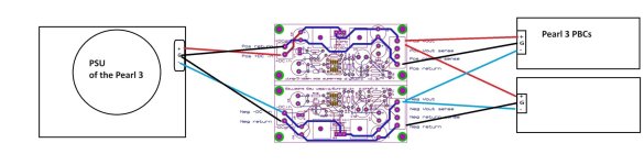
another thing please: i bought the super regulator from the DIY audio store (https://diyaudiostore.com/collections/power-supplies-accessories/products/super-regulator) and i am puzzled with the 4 outputs ... can anyone confirme it is as i drawn it please ?
Attachments
I looked at my post on Jan 1st in the Pearl 3 thread. My setup measured:
121.8 VAC on the wall socket.
+/-25.1 VDC unloaded.
4R7 filter resistors in mine. I shipped 10R in the kits.
Loaded I get + 21.7 / - 22.1
24-25V unloaded (without the pearl 3 RIAA box attached) is perfectly normal.
20-22V loaded is also normal. The P3 boards will use the onboard regulators to get the voltage to +/-15V.
LED resistor Values
The values don't need to be too exact. You can go "rule of thumb" 1k Ohm per volt on the PSU. So 20-25k is fine. I shipped 10k with the group buy parts kits because that's the LED value in the P3 kit. This will result in the same LED configuration in both boxes assuming the same LEDs are used.
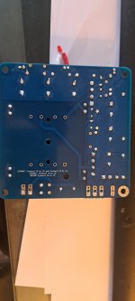
Audio Ground vs Chassis Ground
The reason you get no continuity from Audio Ground (output ground) to chassis ground is because you have the D6 diode bridge acting as a ground breaker. It connects audio ground to earth ground / chassis ground. When the voltage differential between the 2 sides of the bridge is under the bridge forward voltage rating (~1.1V) there is no connection (breaks hum), but when over forward voltage (fault situation) there is a connection for safety.
Snubber resistors
I see you have snubber caps installed, but not snubber resistors. You can install 68R resistors for R1 & R2. I have no idea how the circuit reacts with only partial implementation of snubbers.
Can you measure again:
Output GND to output +
Output GND to output -
Output + to Output -
Output GND and both sides of R9 - 11
Please confirm the resistor values you used:
R3-4
R5-8
R9-11
121.8 VAC on the wall socket.
+/-25.1 VDC unloaded.
4R7 filter resistors in mine. I shipped 10R in the kits.
Loaded I get + 21.7 / - 22.1
24-25V unloaded (without the pearl 3 RIAA box attached) is perfectly normal.
20-22V loaded is also normal. The P3 boards will use the onboard regulators to get the voltage to +/-15V.
LED resistor Values
The values don't need to be too exact. You can go "rule of thumb" 1k Ohm per volt on the PSU. So 20-25k is fine. I shipped 10k with the group buy parts kits because that's the LED value in the P3 kit. This will result in the same LED configuration in both boxes assuming the same LEDs are used.
Audio Ground vs Chassis Ground
The reason you get no continuity from Audio Ground (output ground) to chassis ground is because you have the D6 diode bridge acting as a ground breaker. It connects audio ground to earth ground / chassis ground. When the voltage differential between the 2 sides of the bridge is under the bridge forward voltage rating (~1.1V) there is no connection (breaks hum), but when over forward voltage (fault situation) there is a connection for safety.
Snubber resistors
I see you have snubber caps installed, but not snubber resistors. You can install 68R resistors for R1 & R2. I have no idea how the circuit reacts with only partial implementation of snubbers.
Can you measure again:
Output GND to output +
Output GND to output -
Output + to Output -
Output GND and both sides of R9 - 11
Please confirm the resistor values you used:
R3-4
R5-8
R9-11
Also - I suggest posting questions related the Pearl 3 build in the Pearl 3 thread to get maximum visibility and help. I just happened to stumble onto this post.
Last - what's the idea with the super reg between a CRCRC external power supply and on-board regulators on each Pearl 3 PCB. I'd suggest getting the standard/default build working before modifying.
Last - what's the idea with the super reg between a CRCRC external power supply and on-board regulators on each Pearl 3 PCB. I'd suggest getting the standard/default build working before modifying.
@pougatch
do You know about ripple voltage?
What is your goal to supply the Pearl3?
If you intend to have +/- 15V then your power supply is good enough.
You need post regulator with something like 7815/7915 or LM317/LM337 with divider resistors.
Ripple voltage will rise with load... but in the end will fall (because RMS value will be lower)
For 7815/7915 (LM317/LM337) you will need about 3V difference between input and output (with lowest value of your ripple voltage), but don't forget on input voltage variation (which is defined by your power supplier). Usually this is +/-10%.
So, that is the reason why you have to have so much voltage over the voltage you need for Pearl 3 and its post regulators....
Hi, I tried, I wanted to post on the Pearl forum, but if i am correct i am not entitled to post there... so i went here...Also - I suggest posting questions related the Pearl 3 build in the Pearl 3 thread to get maximum visibility and help. I just happened to stumble onto this post.
Last - what's the idea with the super reg between a CRCRC external power supply and on-board regulators on each Pearl 3 PCB. I'd suggest getting the standard/default build working before modifying.
All right, I understand the super reg is (unecessarilly) complicating and requires modifications on the stock regulation. Faulse good idea... it is just that i read so much about how the PSU and its regulation are important these days that I thought here is an occasion to use it, so as to feed as clean as possible the Pearl... Obviously i was naive
- Home
- Amplifiers
- Power Supplies
- Pearl 3 power supply