It may not be so simple.I don't think it's important to match the JFET CCS currents (Q9 / R27) and seemingly, neither does Wayne C. However if you wish to gild the lily, it's your set of boards and you can build them however you want. Nobody else gets a vote.
I guess you could use a solderless breadboard and some pluggy wires to make a little homebrew jig. It measures the constant current of a J112 JFET and a 220 ohm source resistor (same CCS circuit as Q9 and R27). Then grab your stash of J112s and measure the CCS value of each one, in your jig. Writing down the measured values of course. When all done, choose two J112s that give the most tightly matched constant current sources. Use those two J112s in your Pearl 3.
_
My plan is to assemble the P3 PCB's sans the J112 and 220R resistor and measure the the voltage between the LM7915 output and R36. then you can measure/calculate the real world current through R27 with your potential PF5102's, J111's, J112's that you have in your stash.
Thanks DT
@DualTriode
This discussion reminds me of some advice in the Audio Amateur... forty years ago.
Richard Marsh had proposed a "jig" for matching PNP and NPN pairs -- pair by pair -- for a pre-preamp circuit he had presented.
John Adelsbach suggested simply measuring the betas of each transistor, writing the measurements down and sorting through the two lists for the best matches. Made sense to me then.
The dual cases look beautiful, but I recall seeing a drawing with a panel with adjustable settings.... For one, I want/need three gain settings for .4mV, 1.0mV and 5mV catridges... And I like button and knobs and switches.
Also, I need enough overhead to install tall discrete op-amps that might not quite fit in an 1U chassis unless the board sits low inside. The Burson op amps are about 29mm ( ~1 1/8 inch ).
Also, I need enough overhead to install tall discrete op-amps that might not quite fit in an 1U chassis unless the board sits low inside. The Burson op amps are about 29mm ( ~1 1/8 inch ).
The dual cases look beautiful, but I recall seeing a drawing with a panel with adjustable settings.... For one, I want/need three gain settings for .4mV, 1.0mV and 5mV catridges... And I like button and knobs and switches.
Are you sure that wasn't a photo of your Pearl 2...?

Also, I need enough overhead to install tall discrete op-amps that might not quite fit in an 1U chassis unless the board sits low inside. The Burson op amps are about 29mm ( ~1 1/8 inch ).
Sounds like you'll have a custom order to make with Hifi2000! That's great! @Gianluca will always be happy to help.
Worth mentioning, the pioneer kit from the store will include only what's shown in these photos - All the stuffings for the RIAA boards, except the DRV135 balanced line driver (it's not a inexpensive chip and the people who will want balanced can source it themselves) the RIAA boards, and the empty PSU board.
You'll have to source chassis, of course the Hifi2000 / Modushop option will be available for everybody, and you need get the items to mount to the chassis, jacks, post, plugs, wire, solder, etc... the normal things. There is a fantastic build document from our own @rhthatcher that will have all the BOM, schematic, and lots of reference information. Final editing is in progress right now.


You'll have to source chassis, of course the Hifi2000 / Modushop option will be available for everybody, and you need get the items to mount to the chassis, jacks, post, plugs, wire, solder, etc... the normal things. There is a fantastic build document from our own @rhthatcher that will have all the BOM, schematic, and lots of reference information. Final editing is in progress right now.
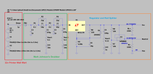
Will split this to a separate thread to deal with low noise SMPS, but I have a beefy HP printer wall-wart, and decided to try Mark Johnson's filter and an off-shelf regulator. Mark's filter yields a tamed waveform (from the printer SMPS which has nasty spikes) and fits nicely under the PSRR umbrella of the LM317. Of course, you can use a Jan Didden SR (replacing the LM317) and rail splitter which obviates the need for the cap multiplier, etc etc.
Attachments
This mention of the balanced line chip prompts a question I've been meaning to ask about order of grounds.
The schematic makes no distinction about signal and power supply grounds and that's OK I guess but I wonder about the connection of pin 1 of the XLR to the ground on the board.
Shouldn't that pin be connected directly to the chassis-shield instead?
The schematic makes no distinction about signal and power supply grounds and that's OK I guess but I wonder about the connection of pin 1 of the XLR to the ground on the board.
Shouldn't that pin be connected directly to the chassis-shield instead?
Are you sure that wasn't a photo of your Pearl 2...?
Sounds like you'll have a custom order to make with Hifi2000! That's great! @Gianluca will always be happy to help.
No, it was (is) a study design for a prototype P3. YOU know that... but now you're just being silly.

Yeah, Gianluca does great custom stuff. Maybe a 5U, 400mm deluxe case, with a 40 lb lead brick inside to give the unit a feel of "heft"!
One comment about the cases... having both cases so alike sort of makes one want to stack them when in reality they should be far apart, huh?
It is, however, a really very nice design.
- Home
- Amplifiers
- Pass Labs
- Pearl 3 Burning Amp 2023