I noticed one thing........ Don´t know if has anything to do with the error, but probably the distortion/low gain??
I see, that you have the low gain jumper on, so presumably using a mm cartridge??
Then you have all 8 dip-switches set to "ON" (closed). That results in almost sompletely choking the signal, even before it enters the
circuit.
Just a suggestion.......... 47K only.
EDIT: Stydying the picture more closely, I might be wrong about the dip-swithches
The pic of the UDP3 has only a neg rail LED lit. The pos LED is not lit. Is that what you see too?
I suspect PS issues if you have both L and R audio boards affected and distorting the same, opamps heating the same. If V(+) is missing, the opamps could be saturating. With only the V(-), the bias LED would still be lit as that part of the circuit is still active.
There would also be DC voltage at the output making the volume of your preamp noisy (if no coupling capacitor) current going through the potentiometer.

t
I suspect PS issues if you have both L and R audio boards affected and distorting the same, opamps heating the same. If V(+) is missing, the opamps could be saturating. With only the V(-), the bias LED would still be lit as that part of the circuit is still active.
There would also be DC voltage at the output making the volume of your preamp noisy (if no coupling capacitor) current going through the potentiometer.
t
The connection of the umbilical ground conductors is curious. It presumes that the +/- grounds on the PSU board are not separate but connected (which -- admittedly without knowing the board design -- I would expect to be done by a deliberate jumper connection).
There seem to be a lot of pads labeled "GND"...
There seem to be a lot of pads labeled "GND"...
Thanks for all the help on this.
I’ve used the UDP3 board before on my first P3 which is why I’m stumped this one doesn’t work.
@runclesid - that picture is taken at an angle but both of those leds are bright green.
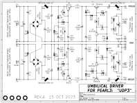
I attached the schematic of @mark Johnson’s UDP3 and it shows all the ground points connected together.
I noticed my leds on the udp3 are a bit brighter than I remember on my first build. I wonder if there are a few parts needing replaced on the UDP3.
The voltages I’ve confirmed are correct at the RIAA boards.
I’ve used the UDP3 board before on my first P3 which is why I’m stumped this one doesn’t work.
@runclesid - that picture is taken at an angle but both of those leds are bright green.
I attached the schematic of @mark Johnson’s UDP3 and it shows all the ground points connected together.
I noticed my leds on the udp3 are a bit brighter than I remember on my first build. I wonder if there are a few parts needing replaced on the UDP3.
The voltages I’ve confirmed are correct at the RIAA boards.
Attachments
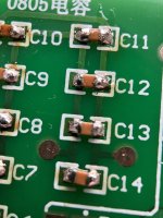
I'm practising as well, have had some success by lightly tinning 1 pad and holding the SMD in place while heating that tab.Not sure how to hold these little guys down.
Not sure as of now with space constraints I had to put it one over the other. Maybe later will try keeping the psu far away and see.@manniraj
how does it sound with the PSU located remotely as specified?
I did mine w tape. I put tape on 1/2 (yes tiny) of the SMD cap. Picked up the tape w the cap and aligned on the PCB. I soldered one side first. Then pulled the tape away and did the other side. Tape burns, but several pieces got it done on the little guys.Got some flux and trying SMDs with it. Not getting much better. Plenty left to practice on before tackling the real thing. Not sure how to hold these little guys down. Not big enough for tape like Jim shows for the ICs.
New update. I ended up changing C21 and 22, checked all solder joints on both boards, removed the 10 ohm/100n ground lift I had on both boards and followed the build guide wiring. I also tested the opamps in my headphone amp and they both still worked fine.
I am still having the same issue but realized I had not checked DC offset yet. 912MV on both channels... I definitely have an issue on both P3 boards.
I am still having the same issue but realized I had not checked DC offset yet. 912MV on both channels... I definitely have an issue on both P3 boards.
Got some flux and trying SMDs with it. Not getting much better. Plenty left to practice on before tackling the real thing. Not sure how to hold these little guys down. Not big enough for tape like Jim shows for the ICs.
A couple of thoughts about how I have done this little solder job.
Preparation:
Clean the PCB down to the shine with 90-99% alcohol.
Snip off the roll of solder 0.81MM Dia. or smaller 1MM long bits of solder.
Have on hand:
tweezers
Tooth picks or orange sticks.
Solder flux paste
Procedure:
Apply flux paste to the PCB solder pads.
With the tweezers place the FET on the PCB
Push the FET into place with the tooth pick or orange stick. Motor control is much more precise with the tooth pick than your feigner tip.
Hold the FET in Place with the tooth pick or orange stick.
Push a clipped off piece of solder next to (touching) the solder pad and FET leg. One little piece of solder is all that is needed.
Heat the joint with the tip of your soldering iron.
Watch the solder melt and draw by capillary action into the joint.
Remove the soldering iron tip from the joint.
Move the toothpick away from the FET.
Wash Rinse Repeat
Examine your work with a loupe.
Thanks DT
6L6 & Randy..what is the function of the 3rd diode bridge (D6)? Would the simple combination of the initial two bridges (as a common ground) be too noisy or are there other reasons?@rhthatcher Has made a great little PCB with CRCRC filtering for the raw supply. Ive got a few to try, as well as some other solutions… this is going to be fun!
View attachment 1222037
Thanks!
The PSU transformer has dual secondary windings. One winding is used for the positive rail, and the other is used for the negative rail.
D1 is positive rail rectifier bridge
D2 is negative rail rectifier bridge
D6 is a ground break bridge. It connects audio ground to earth ground / chassis ground. When the voltage differential between the 2 sides of the bridge is under the bridge forward voltage rating (~1.1V) there is no connection (breaks hum), but when over forward voltage (fault situation) there is a connection for safety.
There are many possible ways to implement a ground break, and this board uses the philosophy from the previous Pearl PSU. Other ways include a thermistor (see First Watt power amps), 3W resistor at 5-15 Ohms, R with cap in parallel, 2 diodes, 2 diodes / R / Cap.
Last edited:
New update. I ended up changing C21 and 22, checked all solder joints on both boards, removed the 10 ohm/100n ground lift I had on both boards and followed the build guide wiring. I also tested the opamps in my headphone amp and they both still worked fine.
I am still having the same issue but realized I had not checked DC offset yet. 912MV on both channels... I definitely have an issue on both P3 boards.
A few more things I checked last night. The Toshiba transistors are in the correct positions facing the right way. Same for the ZTX Q5 and Q8 transistors. The high Voltage at the outputs makes me wonder if somehow I am getting high DC into the U1 after reading the below in an earlier thread.
Does anyone have any voltages I could check at the opamp to help narrow down the issue? Thanks!
"DC offset will be essentially equal to the Input Offset Voltage of U1 opamp"
- Home
- Amplifiers
- Pass Labs
- Pearl 3 Burning Amp 2023