SkinnyBoy said:if by scanning and posting this I have violated any copyright laws, feel free to let me know.
This amp will have several fundamental limitations. It looks simple, but depends on the goal you have - simplicity or sound qality? This amp will have bad behaviour on high frequencies (long turn-off times, as there are no resistors in Darlingtons) and no care has been done to set up correct bias current, you can expect distorted high midrange and highs, NFB do not have a chance to correct it, especially high frequency distortion products.
Hello Skinnyboy,
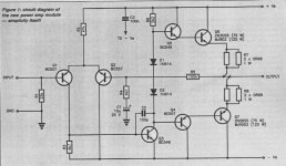
Just incase you don't all ready know, this schematic is a DIGI 125 designed and sold by Graham Dicker of Adelaide.
http://members.bettanet.net.au/~gtd/kits.html - Scroll down a page or two.
There has been a couple of significant threads discussing this amplifier and suggesting improvements. In summary, use toshiba 5200/1943 output transistors, add 1 extra bias diode, upgrade VAS transistor and add a bootstrap on the VAS.
I've built one, and with the extra changes have been very surprised with the performance.
Also, have a look at two of Destroyer X threads:
http://www.diyaudio.com/forums/showthread.php?s=&threadid=38616
http://www.diyaudio.com/forums/showthread.php?s=&threadid=35899
These show circuits with similiar topology but with a few extra parts.")
Just incase you don't all ready know, this schematic is a DIGI 125 designed and sold by Graham Dicker of Adelaide.
http://members.bettanet.net.au/~gtd/kits.html - Scroll down a page or two.
There has been a couple of significant threads discussing this amplifier and suggesting improvements. In summary, use toshiba 5200/1943 output transistors, add 1 extra bias diode, upgrade VAS transistor and add a bootstrap on the VAS.
I've built one, and with the extra changes have been very surprised with the performance.
Also, have a look at two of Destroyer X threads:
http://www.diyaudio.com/forums/showthread.php?s=&threadid=38616
http://www.diyaudio.com/forums/showthread.php?s=&threadid=35899
These show circuits with similiar topology but with a few extra parts.
hehe, triangle!... i found that too... and try the square in low frequency!
This thopology is magnificent in sonic qualities...but not so simple that way.... need more components, and not easy to discover without long and deep research.
The way it is..... hummmm...look the triangle wave shape at 10 Khz and imagine the sound result?
No, i am not telling that waveshape is the quality "dictator"....not that....sometimes sounds good too....but, related to standards... lets say, need some little job to be very good.
Carlos

grege said:Hello Skinnyboy,
Just incase you don't all ready know, this schematic is a DIGI 125 designed and sold by Graham Dicker of Adelaide.
yeah... I have a photo copy of the article published in the May 1989 issue of ETI...
I probably won't make this... actually.. I probably already have all the parts lying around...
I actually have a feeling this is a very similar circuit to what is used in an amp I have... might look into that.
Rather than pointing out the limitations of the circuit, consider how and wgere it might best be used. The virtues are, of course, dirt cheap, very small PCB footprint (could probably be done on veroboard), no set-up adjustment, so easy to build it should function to spec on the first try.
Apart from pedagogical uses, it is suitable where funnctionality and/or "good enough" are considerations. It would shine where a very modestly power PA amp is needed. I could also be used to construct a set of powered PC "multimedia" speakers. Considering what is offered commercially for such applications this would sound better than the majority.
In the spirit of making it even simpler, cheaper, and smaller I would suggest the following: A- replace the two bias diodes with a single green T-1 LED, B- use TIP2955 and TIP3055 output devices (they are good enough, small and cheap), C- the applications I've suggested don't need rails higher than about +/-25Vdc.
This will never be in the same league as a Krell (or even a P3A) so don't beat a dead horse - instead captalize on it's virtues.
sam9,
unfortunately I cannot agree with you at all. There are several basic design flaws as it was designed by a primary school pupil. For example, just add resistors of 100 Ohm between B and E of the output transistors and the circuit is one class higher. I do not know why to apologize mistakes like this. Also, the output circuit is completely underbiased. Why not to add just one diode? It will remain underbiased (no problem with thermal runaway), but not that horribly. Last but not least, currents of the input LTP are completely unbalanced. The right value of the collector resistor is not 4.7k, but about 2.7k. This will reduce output DC voltage considerably.
unfortunately I cannot agree with you at all. There are several basic design flaws as it was designed by a primary school pupil. For example, just add resistors of 100 Ohm between B and E of the output transistors and the circuit is one class higher. I do not know why to apologize mistakes like this. Also, the output circuit is completely underbiased. Why not to add just one diode? It will remain underbiased (no problem with thermal runaway), but not that horribly. Last but not least, currents of the input LTP are completely unbalanced. The right value of the collector resistor is not 4.7k, but about 2.7k. This will reduce output DC voltage considerably.
Hi all,
I agree with you sam9. I believe the value of this circuit is its educational value. This is probably the most basic cirucuit that will actually work. In its basic form it is NOT the best amp in the world. Once you have the basic amp working you can add the components recommended in the various DIGI125 threads and see for yourself if these changes improve in amp's performance.
This is what I have done and have really enjoyed the experimenting process. Half way through this process you end up with a GOOD amp. (still not the best). I believe this amp has the potential to be VERY good.
I believe some of the experts can forget the importance of these intermediate steps in learning the ropes of the amp building process.
I don't have a Krell, but I prefer my DIGI125 to my P3A, but this is a personal preference because the P3A is a good amp. Obviously, the P3A is a better designed amp than a DIGI125 amp modified by a committee and me (I don't really know what I am doing )
I have added these and there was a slight improvement in the clarity of amp. I recommend leaving these in.
Exactly right! The extra diode makes a difference, but it is still underbiased. The output transistor never get hot, not even warm.
The first test I do when adding or changing a component is test the DC offset and have never had a problem as it is always less than 50mV. Generally, as I add components the offset tends to reduce. Why?
A little bit harsh Mike. In the DIGI125 article, Graham Dicker tells us he designed this amp to be small, cheap, simple to assemble and requires no bias adjustment. Originally this amp cost only about $30 and currently costs $49.
Obviously I don't agree with this. It really comes down to your expectations. I believe for most, it is a valuable and useful exercise and not a waste of money. I use my DIGI125 regularly even though I have a better amp.
I agree with you sam9. I believe the value of this circuit is its educational value. This is probably the most basic cirucuit that will actually work. In its basic form it is NOT the best amp in the world. Once you have the basic amp working you can add the components recommended in the various DIGI125 threads and see for yourself if these changes improve in amp's performance.
This is what I have done and have really enjoyed the experimenting process. Half way through this process you end up with a GOOD amp. (still not the best). I believe this amp has the potential to be VERY good.
I believe some of the experts can forget the importance of these intermediate steps in learning the ropes of the amp building process.
Originally posted by sam9
This will never be in the same league as a Krell (or even a P3A) so don't beat a dead horse - instead captalize on it's virtues.
I don't have a Krell, but I prefer my DIGI125 to my P3A, but this is a personal preference because the P3A is a good amp. Obviously, the P3A is a better designed amp than a DIGI125 amp modified by a committee and me (I don't really know what I am doing
)Originally posted by PMA
For example, just add resistors of 100 Ohm between B and E of the output transistors and the circuit is one class higher.
I have added these and there was a slight improvement in the clarity of amp. I recommend leaving these in.
Originally posted by PMA
Also, the output circuit is completely underbiased. Why not to add just one diode? It will remain underbiased (no problem with thermal runaway), but not that horribly.
Exactly right! The extra diode makes a difference, but it is still underbiased. The output transistor never get hot, not even warm.
Originally posted by PMA
Last but not least, currents of the input LTP are completely unbalanced. The right value of the collector resistor is not 4.7k, but about 2.7k. This will reduce output DC voltage considerably
The first test I do when adding or changing a component is test the DC offset and have never had a problem as it is always less than 50mV. Generally, as I add components the offset tends to reduce. Why?
Originally posted by mikeks
There are several basic design flaws as it was designed by a primary school pupil.
A little bit harsh Mike. In the DIGI125 article, Graham Dicker tells us he designed this amp to be small, cheap, simple to assemble and requires no bias adjustment. Originally this amp cost only about $30 and currently costs $49.
Originally posted by mikeks
Whatever you do...don't waste time and money building this amp.....
Obviously I don't agree with this. It really comes down to your expectations. I believe for most, it is a valuable and useful exercise and not a waste of money. I use my DIGI125 regularly even though I have a better amp.
The extra diode makes a difference, but it is still underbiased. The output transistor never get hot, not even warm.
This is a rather nice feature for a learning project for a beginner. Reduces the chances of smoke and flames on first power up, an event that can be quite discouraging to say the least.
Another possibility would be to make it an "Edwin" amp just by adding one more diode and two resistors. This would still not be highend but it could improve the amp considerably while still being a KISS solution.
That's how it goes:
You would have to use another series bias diode so that you would end up with 2.1 volts approx. You now have to connect a resistor between each driver's emitter and the output node. This would give a small "class A" amp driving a class-B output stage. The value of the resistors are depending on the capabilities (current and dissipation) of the drivers.
One remark: IMO the proposed driver transistors are a little underdimensioned even for a class B amp.
Regards
Charles
Edit: I didn't read well enough what Pavel wrote but he said basically the same thing as I did.
you've got the point here manhjelm said:Isn't the biasing a little low with only 2 diodes versus 4xVbe+2xVremitter?
although vintage, it isn't complete
there should be at least 4 diodes or 2 diodes and a small potentiometer in series
cheers
pa600 or super leach amp
Hi Eva,
I am confused here on building a high power amp , should I go for leach super amp or pa600 suggested by oliver,
I was intending to go for leach super amp but was hesitent when i saw your opinion on the recent forum.
please guide me on this matter
thanks
arasuk
u can mail me also at arasukumar@yahoo.com
grege said:
A little bit harsh Mike. ....
You've got the wrong man mate...i didn't say anything about primary school projects....
http://diyaudio.com/forums/showthread.php?postid=458660#post458660
- Status
- This old topic is closed. If you want to reopen this topic, contact a moderator using the "Report Post" button.
- Home
- Amplifiers
- Solid State
- Peace!!!!