Ken was suggesting that DAC's in differential will cancel the 2nd harmonic. I took what Boky posted as "support" for that position - sorry if I misconstrue.
I agree with you, non-common mode 2nd order distortion products present at the input of the differential amplifier will get amplified for sure!
Boky
I don't agree with this, the last BB design with these DAC's, the PCM1702 reference board has 4 PCM DAC's in parallel per channel, almost all high end designs parallel pcm1704's, the minimal increase in linearity is certainly not audible (we aren't talking about tda1543s here.)
It is obvious that the increased current output helps the output stage performance. The BB engineers knew that the low current combined with low output impedance current source was a bottleneck only helped by using more chips.
The current will increase, yes, but this is not necessarily a good thing, depending on the I/V circuit design. The multipled signal current swing created by paralleling DACs places much greater signal amplitude demands on the I/V, almost certainly provoking greater THD in the I/V than would a smaller signal current swing. An improved SNR is only one impact of paralleling.
In addition, paralleing current DACs makes the composite output impedance go down. Not a good thing in most cases.
Last edited:
Well, the ones that make those harmonics... Fhe fundamental signal. I don't see why the harmonics won't be reversed too, if the base signal is reversed. Especially why some (odd order) of the harmonics would be in phase and the other (even order) would be out of phase.
They will be all in reverse phase with respect with each other, because they follow the fundamental signal.
Remember, this is not statistic noise!
Noise is un-correlated, we are talking about correlated components. You have keep in mind what even order distortion looks like in the time-domain. It manifests as an asymmetry of the signal waveform. Inverting the waveform therefore also inverts this asymmetry, re-establishing waveform symmetry upon analog algebraic summation. Again, this is a well established open-loop distortion canceling principle, one which has been utilized in push-pull and complementary symmetry amplifier topologies for decades.
Last edited:
You are wrong, inversion is a symetrical, linear operation. Distortion will invert also when the input signal is inverted. The second-order harmonics in DAC#2 don't "know" that the signal passing thru DAC #2 is inverted in respect to the signal that passes trough DAC#1.Inverting the waveform therefore also inverts this asymmetry, re-establishing waveform symmetry upon analog algebraic summation.
Inverting a distorted wave will not CHANGE the shape of that wave. Like I said, inverting a square wave will not sudennly make it a triangular one - that would happen if the second harmonic will change differently from the fundamental or the third one.
Last edited:
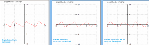
Acually, look at pictures below. First is a "normal" signal with 2nd a 3rd distortion. Second is the same signal inverted completelly (as it happens in reality). Note that the shapes are in mirror, as they should.
The third is what you say it happens - the second harminic is not chaging the phase as the rest of the signal. Note that the resulting signal is not at all "mirrored", it changes shape. It is NOT an inverted signal for the original one.
The third is what you say it happens - the second harminic is not chaging the phase as the rest of the signal. Note that the resulting signal is not at all "mirrored", it changes shape. It is NOT an inverted signal for the original one.
Attachments
You are wrong, inversion is a symetrical, linear operation. Distortion will invert also when the input signal is inverted. The second-order harmonics in DAC#2 don't "know" that the signal passing thru DAC #2 is inverted in respect to the signal that passes trough DAC#1.
Inverting a distorted wave will not CHANGE the shape of that wave. Like I said, inverting a square wave will not sudennly make it a triangular one - that would happen if the second harmonic will change differently from the fundamental or the third one.
The distortion doesn't invert (whatever you mean by that), the waveform inverts. Therefore, waveform asymmetry is also inverted. Upon algebraic summation of the two anti-phase waveforms the original waveform asymmetry cancels. This has long been a well known and exploited engineering fact about push-pull and complementary symmetry circuits. I'm repeating myself, which means that there's no point in further discussion. I suggest that you do a simple web search to see all the many papers confirming what I've told you. References to it are everywhere in the engineering literature.
Push?pull output - Wikipedia, the free encyclopedia
http://www.analog.com/library/analogDialogue/archives/43-09/EDCh 6 Converter.pdf See page 6.24
Last edited:
The distortion doesn't invert (whatever you mean by that), the waveform inverts. Therefore, waveform asymmetry is also inverted. Upon algebraic summation of the two anti-phase waveforms the original waveform asymmetry cancels. This has long been a well known and exploited engineering fact about push-pull and complementary symmetry circuits. I'm repeating myself, which means that there's no point in my further hitting my head against this wall.
Push?pull output - Wikipedia, the free encyclopedia
http://www.analog.com/library/analogDialogue/archives/43-09/EDCh 6 Converter.pdf See page 6.24
Ken you still don't understand what we are saying, what you propose will work if you want a 0VAC output dac
")
The harmonics we are talking about are the signal prior to the analog stage.
We aren't operating the DAC chips in push/pull or complementary
Here is an example:
A tube circuit with a gain and phase spliter. There is now 2H on each phase. Now we send this to our push-pull output stage, here the 2H of the output tubes can be cancelled. But the incoming 2H from the gain stage remains.
There is such a thing as single ended 2H cancelation in a stage like a loftin-white, is that what you are proposing? We can't do that here because the DAC chip is where the 2H originates.
Surely you know this and this is just a communication gap.
Ken you still don't understand what we are saying, what you propose will work if you want a 0VAC output dac
The harmonics we are talking about are the signal prior to the analog stage.
We aren't operating the DAC chips in push/pull or complementary
Hmm, I also suspect there is a failure to communicate here
Isn't the context of the discussion precisely a pair of DAC outputs operated differentially in push-pull anti-phase? Perhaps, we're are talking past each other and will continue to do so, but I'll take one last stab.
Imagine a pair of single-ended amplifier stages (instead of two DACs) operated as a balanced bridge. Each SE stage on it's own produces significant amounts of 2H, but when operated differentially the 2H greatly cancels. The now push-pull circuit doesn't produce 0 volts, but rather a differential voltage swing twice what either SE stage does alone - all while cancelling the 2H. It doesn't matter that the 2H existed right at the inception of the signal chain, prior to the two anti-phase signal being summed in to an single in phase signal, the 2H will still cancel, wouldn't you agree?
If I correctly recall (and, I may not) Loftin-White utilizes anti-phase current signals, similar to how the SRPP works in that respect, although they are different in other respects. If it is push-pull, anti-phase in either current or in device conduction, it will tend to cancel even order distortion products. Again, this is all so basic there must be some mutual misunderstanding of context or something taking place here.
Last edited:
Hmm, I also suspect there is a failure to communicate here
Isn't the context of the discussion precisely a pair of DAC outputs operated differentially in push-pull anti-phase?
I don't think you can operate a DAC chip in that manner, you need an anode and a cathode for each device (or emitter/collector.) These DAC's are just a low impedance current source (I know that's an oxy-moron.)
What we are talking about is a separate I/V opamp for each phase/DAC chip, followed by a summing opamp thats usually serving as a buffer with filtering. So we cancel any part of the signal that is of the same phase. Typically mains frequency and its harmonics, so that could help the THD number.
The problem is most of the two DAC chips intrinsic distortion is going to be of opposite phase and summed just like the rest of the signal.
The closest I have seen to a current mode P-P is Lazslo's I/V,
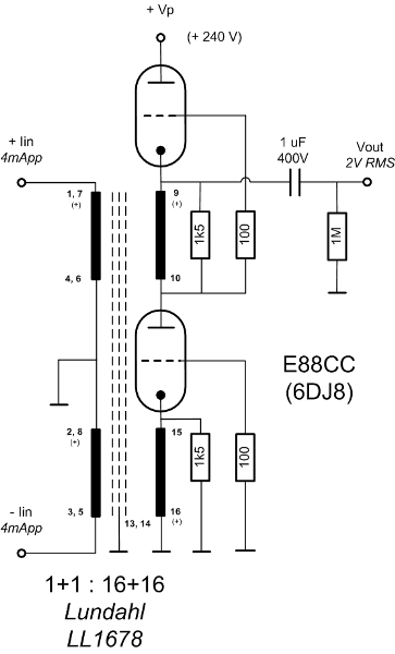
but the THD is much higher than the separate opamp approach due to the iron and tubes. It would be interesting to try something like this with BJT's for the impedance buffering and amplification but I haven't seen it done, have you ?
The main isssue is that the DAC is single ended inside the chip. Distortion products that are produced INSIDE, cannot be canceled OUTSIDE. Inversion at that point inverts the whole signal.
Ken, just look at the graphs above and the formulas that generate them. You will see that only a fully inverted signal (fundamental and ALL harmonics) will be mirrored image of the original.
The push-pull canceles the distortions produced INSIDE that stage, compared to a SE stage with class AB polarization. A SE class A will have less distortions (of any order) than any push-pull.
You just read somewhere that "2nd order harmonics are canceling" and, because you wish to be true, you assume that's true (for all situations).
You chose to ignore other "details" or "ideas" or "math" that don't fit to your desire.
That's a lot like a religion and I won't fight that.
Last edited:
As I said, this mechanism has been known and exploited for literally decades - see the linked paper from 1953 below. Regal, be sure to read the middle column of the first page regarding the false notion that transformers are required. Sonic, it's complete nonsense for you to suggest that even order distortion originating 'inside' a gain stage can be cancelled, but somehow, even order distortion originating inside a DAC cannot be. If a DAC output exhibits even order distortion (which, they do), then operating two of those outputs in push-pull will cancel that distortion. Geez, this stuff is elementary. There's nothing constructive left for me to say about this.
http://www.pearl-hifi.com/06_Lit_Archive/02_PEARL_Arch/Vol_01/Sec_1/0015_Simplified_PP_Theory.pdf
Oh, and, Sonic, stop it with that pious hogwash about crusading against false religious beliefs. This is engineering. Perhaps, if you were less reflexively (and offensively) certain of your own view you might not look so foolish in most of these debates.
Last edited:
The main isssue is that the DAC is single ended inside the chip. Distortion products that are produced INSIDE, cannot be canceled OUTSIDE. Inversion at that point inverts the whole signal.
yes exactly we can't acces the top of the r2r ladder! I haven't even heard of a discrete DAC push-pull desn (meaning shared I/V), Ken if you know of one please share, and of course push-pull doesn't require transformers.
But back to the original topicon the opamps I found an interesting paper here:
http://www.iet.ntnu.no/courses/fe8114/files/Report_audiodac.pdf
I know others favor the open loop transimpedance discrete designs. But I guess I am a missouri type:show me (my first job as an engineer at a chemical company always said that.)
I mean we can find literally dozens of 1kz FFT's of opamp output stages with no harmonics above -100db posted on the web. Yet for discrete BJT open loop, the best I could find was Rogics diamond I/V where he has a -80db 2H. And there are many mentions of stability issues with BJT I/V's, I think designing a open loop BJT needs an RF there would have to br some local feedback/degenerative 2H cancellation because the best you can do dumping an i-out into a BJT emitter is about -80db 2H. This is because a BJT is a much less linear device than a triode, jfet, or mosfet.
I have tried the jfet version of the pass D1 (again discrete open loop), and it had more distortion than a very basic resistor i/v plus triode anode follower. Plus it the jfet D1 had nearly the same amout of input impedance as the passive i/v.
However there have been major improvement to using Jfets as an altenate open loop I/V with the advent of the Zen and the Sen, I haven't tried these yet. But again there is much more evidence with the original D1 the semisouth D1, now the Zen (both Pass designs) and its offshoots CEN/Sen have showed much more promise for an open loop I/V for the hobbyiest as an alternative to opamps.
So as an emperical type the 2012 state of the R2R I/V stage alternatives looks like this:
VFB opamp
CFB opamp
D1 variants
Zen &Jfet variants
Discrete opamps
Passive + gain (jfet or tube)
I have a dual differential PCM1704 DAC that time permitting, going to try then all.
This is with the passive I/V +jfet gain+jfet diamond buffer as a starting point.
(single ended output which isn't sumed), surprisingly good considering the I/V resistor is 40 ohms! Surely can do better.
Last edited:
I really didn't mean to start an argument about differential dac operation, though I must say that I do agree with Ken on this issue.
It would be nice if we could get back to the original subject, which is, IIRC, making best use of the 1704's BPO & servo pin functions.
Well its related. I just bought an old Parasound HD1100HD (PMD100-PCM63K). In the manual it said the PCM63K's were run in push-pull for balanced output. Tha damn online manual was wrong and this only has 2xpcm63k's and unbalanced output but I bought it anyway.
But I've never seen a PCM63 output like this, look at how the pins for the current are all accessible (compare the 63 vs 1704 datasheets), . I think this answers the question. The PCM1704 is sort of a less featured pcm63 (even though they keep selling out at $70/peice from digikey.) Heck the THD performance is about the same.
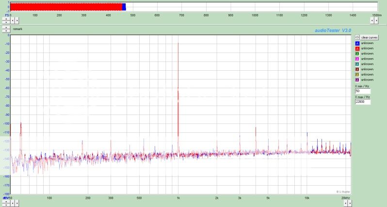
Numbers wise the complete implementation has more THD & IMD than my over PCM1704 +passive I/V+jfet gain+diamond buffer.
But its only because of powersupply quality (120hz and its harmonics are the dominate distortion.) Or rather the PSRR of the old opamps. Fun to play with but would have been better if it had the 4xpcm63 in push-pull.
A very kind soul on this forum is sending me a Jac No3 PCB to experiement with as well.
I also have a PMD100-AD1862 that will be getting the Sen I/V.
Last I am throwing in the hifidino wolfson wm8741 as a S-D comparison.
So maybe when I am done I can finally comfirm Borbely's description of the PCM1704 as the best DAC chip ever made. I missed the chance to buy his 1704 kit.
Last edited:
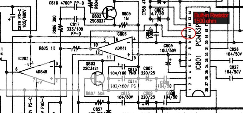
The only difference between two DAC's is in the way BPO error voltage (as the result of high compliance voltage) is added to Iout. With PCM63 you can break the link between pin 5 and 6; with PCM1704 that link is done internally. Rf is also on a die with PCM63 giving better linearity.... I doubt this makes too much of a difference compared to low noise non-inductive external resistor of 0.1% tolerance.
I suppose if you can not measure any voltage at inv pin of the CFB amp, even with something crazy like 1kHz 0db squarewave signal AND you can not measure any voltage at frequencies from 20-20kHz with 0dB sinewave, the impedance will be negligible across the whole audio range and certainly very low to never trigger the BPO circuitry in the first place....I have improved the circuit based on AD811 IC….. and can not measure any voltage at inv pin of AD811, with signals I mentioned above... all I see is the noise floor now.
On a similar note, I have checked this thread tonight:
http://www.diyaudio.com/forums/digital-line-level/161845-list-dacs-under-450-a.html
… and was impressed by what you can get for around $400 - $700…. I’d single-out the AMB y1 and y2… as well as this one: NOS Mini DAC Octave.
There’s another DAC at the similar price range, the Musical Fidelity M1 -> which I think has great potential as well, mainly due to excellent PCB design.
If anyone has experienced any of these, pls share the opinion.
Boky
A very kind soul on this forum is sending me a Jac No3 PCB to experiement with as well.
JT DAC No3 is another example of an excellent PCB design... but where are you going to find 1702?
Boky
JT DAC No3 is another example of an excellent PCB design... but where are you going to find 1702?
Boky
I was just going to use PCM1704K, I thought the 02's and 04's were just mainly pin compatible different gradings, same i-out mA & impedance,but I guess I've never looked at an '02 datasheet.
They are not pin compatible. Pins 4 & 6 (+/- Vdd) are swapped.I was just going to use PCM1704K, I thought the 02's and 04's were just mainly pin compatible different gradings, same i-out mA & impedance,but I guess I've never looked at an '02 datasheet.
JT DAC No3 is another example of an excellent PCB design... but where are you going to find 1702?
Boky
I see that the JT No3 uses the thru-hole version of the PCM1702, luckily they are still on the shelf too.
But I may have adapter pcbs made for the smd '04, may be able to swing closer decoupling with modern smd caps if the adapter board could be considered a decent ground plane. Lots of fun ahead!
Appreciate all the help and suggestions from this thread.
- Status
- This old topic is closed. If you want to reopen this topic, contact a moderator using the "Report Post" button.
- Home
- Source & Line
- Digital Source
- PCM1704 Vref & ServoDC, 12 years and still a secret?