PCBs to build the preamplifier are still available.
The price for one PCB is 28 Euros, including shipping.
The construction is described here:
https://audioxpress.com/article/you-can-diy-the-pr-3-a-high-quality-stereo-preamplifier
The price for one PCB is 28 Euros, including shipping.
The construction is described here:
https://audioxpress.com/article/you-can-diy-the-pr-3-a-high-quality-stereo-preamplifier
")
PCBs to build the PR-3 preamplifier are available.
The price for one PCB is 28 Euros, including shipping.
For the construction see here:
https://audioxpress.com/article/you-can-diy-the-pr-3-a-high-quality-stereo-preamplifier
The price for one PCB is 28 Euros, including shipping.
For the construction see here:
https://audioxpress.com/article/you-can-diy-the-pr-3-a-high-quality-stereo-preamplifier
Hi to all,
Hi George,
I proceed with your pre-Phono MC project. Until now seam all OK. I finished the mounting phase of the two channel. All of it function.
Now I'm building the "INVERSE RIAA" for check the output and, in the same time, I'm starting in mounting phase for the PR3 project
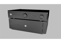
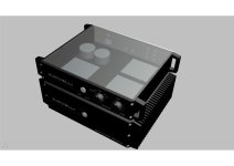
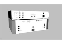
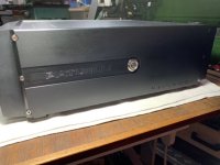
With my CAD I drew the case for preamp+pre-phono MC in rack with the Power Amp already finished.
I attach some pictures of WIP.
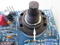
George, one ask: I received the rotary switch 6 pos 2 pole for the input. But how I can use or stop the 6th position? In the front panel I marked only 5 and I don't like a empty position of the selector.
If you have an idea it will be appreciated.
Thanks to all for your attention and at soon for progress.
Andrea
Italy
Hi George,
I proceed with your pre-Phono MC project. Until now seam all OK. I finished the mounting phase of the two channel. All of it function.
Now I'm building the "INVERSE RIAA" for check the output and, in the same time, I'm starting in mounting phase for the PR3 project
With my CAD I drew the case for preamp+pre-phono MC in rack with the Power Amp already finished.
I attach some pictures of WIP.
George, one ask: I received the rotary switch 6 pos 2 pole for the input. But how I can use or stop the 6th position? In the front panel I marked only 5 and I don't like a empty position of the selector.
If you have an idea it will be appreciated.
Thanks to all for your attention and at soon for progress.
Andrea
Italy
Attachments
-
 IMG_6820.jpg66.8 KB · Views: 56
 -
 IMG_6819.jpg46 KB · Views: 58
 -
 IMG_6818.jpg43.2 KB · Views: 49
 -
 front5B.jpeg19.1 KB · Views: 48
 -
 inside4.jpeg24.1 KB · Views: 50
 -
 back5.jpeg19.8 KB · Views: 60
 -
 40A78978-999C-4D46-A3A1-E81C83FC957F.JPG37.8 KB · Views: 60
 -
 IMG_6008.jpg69.9 KB · Views: 58
 -
 IMG_6048.jpg61.4 KB · Views: 68
Very nice work Andrea!
I am sure you will enjoy also the sound!
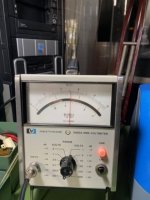
For the 6 positions 2 pole switch see the attached photo.
You could remove the metal stop with a small screwdriver and then put it again at the position you want.
In the photo it is set in position 6 but you can see all the other positions.
George
I am sure you will enjoy also the sound!
For the 6 positions 2 pole switch see the attached photo.
You could remove the metal stop with a small screwdriver and then put it again at the position you want.
In the photo it is set in position 6 but you can see all the other positions.
George
Attachments
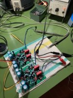
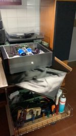
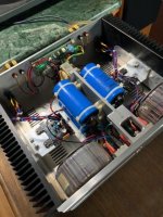
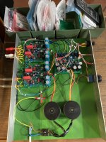
Hi to all, some updates. I assembled PR3 and MC100, on a temporary wood table for check the good function of all.
First of all I changed the stylus head from MM to MC (Denon DL103); I adjusted with the trimmers the output offset in order to measure 0 VDC at the preamplifier’s output. Then Volume! The couple PR3-MC100 works great. A very clear sound and a great effect of presence. Great work George!
Now I will start in the construction of final box with all the tricks to contain the noise. About this issue: # George, what do you think if for each input wires (6) I use a shielded wires? I noted also (in this temporary assemble ) that touching with my hand the pot Alps wires to the pcb , I fell noise. Only touching! Also here I could use a shielded wires?
Looking my pictures, any suggestion will be appreciated.
Many thanks
Andrea
Attachments
Hi Andrea,
Nice! I'm glad to hear your excellent progress.
Concerning your questions:
1. I recommend to arrange the PCBs in order to have the shortest length of cables. Try to have the PR-3 pcb close to the RCA connectors.
2. Keep the transformers as far as possible from the PCBs especially for the MC-100.
If possible use a piece of metal shield between the transformers and the PCBs.
3. I always use shielded wires for every audio signal, even the shortest ones.
George
Thanks George for your support.
The PCBs layout is not a easy thing. Now I have favorite the shorter wires length of pre-phono input (smaller signal) So I thought. 3 PCB all together on back close to the RCA connectors is not possibile.
About the shielded wire, Can I always use the shield for the negative connection? Es. for the signal IN CD/AUX/PHONO from MC100 I buy a wire with one conductor inside and a external shield. For pot ALPS wires, 2conductor inside and one shield. It's right? Sorry but I dont have a practice with this wires connections.
A idea of last minute : I'm thinking to leave more space between the two MC100. I move, on back panel, the group of RCA connector in front the clearance between the two MC100. Last I move the PR3 until the IMPUT wires could pass throughout the two MC. In this way I can reduce a lot the length of input wires.
Could be?
Andrea
Hi Andrea,
I think it is a good layout. But you can never be sure until you built it.
So, I would suggest to make all the cabling without permanent support of the PCBs to the metal box.
Just to check that there is no noise.
Concerning the shielding of the cables: yes, use the shielding to the negative (ground) connection in both cases (inputs and volume).
George
Hi Geroge,
I have not yet assembled my board. I was looking at the rc input snubbers, c3/r18; r22/c32 and I was wondering if those parameters were specific to your transformer, or kind of universal to any similar transformer uses. Tks.
No, they are not specific.
They were recommended as universal snubbers in a article in Linear Audio magazine, if I remember correctly,
George
 A lot of work (with love) and a great soddisfaction.


