I wonder if one of you would check my math/assumptions. I am about to start building the XA252 with two 300va toroids (28v) and Randy's W12 PSU. Following the equation from post #1, it seems 12x 33k uF caps would result in an inrush of ~256J and 12x 22k uF caps in ~171J. This seems high, but if correct, using 22k uF caps in combination with the 250J ICL would stay within the limits of the soft start module?
Thanks -
Soren
Thanks -
Soren
Math looks approximately correct; I got 295J and 197J respectively.
If you are nervous you could connect two 250J inrush current limiter discs in series (certainly NOT in parallel), attach them to a high current terminal strip somewhere handy on the chassis, and route very beefy flywires between the ICL discs and the ICL solder-pad holes on the PCB. Now you're good for 500 Joules of inrush energy.
Or you could imagine having two H9KPXG boards inside your chassis, one for each of your two toroids. Now each board services the inrush of six BigOleBohunker electrolytic caps, rather than twelve.

i have read the entire thread. Many thanks Mark for educating and sharing your design and also those who contributed to this informative discussion.
Is there a need for a soft start for SMPS supplies, perhaps with time delayed relay bypassed ICL in the DC path after the SMPS?
Is there a need for a soft start for SMPS supplies, perhaps with time delayed relay bypassed ICL in the DC path after the SMPS?
I think you'd have to connect your specific apparatus to reasonable quality test equipment including a current probe, and see how big the inrush really is.
For linear supplies with a power transformer, I used (this gear (post #41 of another discussion)) to measure currents, with and without H9KPXG.
For SMPS supplies you might want to do two sets of inrush current measurements; one to measure inrush on the AC mains, and another inrush measurement on the DC output from the SMPS. There might be gigantic currents at startup when the SMPS tries to charge up all of the capacitance of the equipment it is powering. If the output current happens to exceed the SMPS's built in current limit, then you may enter Hiccup Mode and remain stuck there forever.
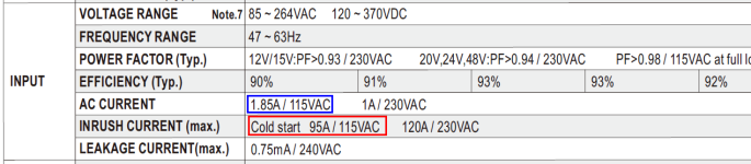
Attached below is a datasheet of the SMPS that Nelson Pass specified for the VFET lottery amplifiers here on diyAudio. This SMPS has an inrush current (drawn from the AC mains when the SMPS is turned on) greater than 90 amperes (120 amps in Europe). If you are concerned that this huge current will stress your power on-off switch, and/or mains fuse, and/or the home circuit breaker, then a soft start can bring peace of mind. It's a human judgement call.
_
_
Attachments
I am also building XA 252 with two 28 volt 300VA Anteks. Rather than the CL-60 setup, I thought I would use soft starts. Initially I was going to use the store version, but I see another member is going down the same road, with these soft starts. My power supply is dual mono, with four 33,000 50 volt caps per side. Is one of your devices sufficient? Sounds like using one for each channel is best? That is my uneducated preference.Math looks approximately correct; I got 295J and 197J respectively.
If you are nervous you could connect two 250J inrush current limiter discs in series (certainly NOT in parallel), attach them to a high current terminal strip somewhere handy on the chassis, and route very beefy flywires between the ICL discs and the ICL solder-pad holes on the PCB. Now you're good for 500 Joules of inrush energy.
Or you could imagine having two H9KPXG boards inside your chassis, one for each of your two toroids. Now each board services the inrush of six BigOleBohunker electrolytic caps, rather than twelve.
Thanks,
Russellc
@Russellc
Read the 1st post on this thread under “(optional tech info): MORE ABOUT INRUSH LIMITER JOULE RATING”
Go through the scenarios Mark Johnson has detailed, working out the math for yourself. Then, try and see if you can calculate the total number of joules for each channel since you have a dual mono power supply. You will then know if you need 2 separate soft start boards with two separate ICL thermistors or if one soft start board with one ICL thermistor can accommodate the joule rating of the supply. There are of course other options such as series connecting two ICL’s together for a larger joule rating and the use of one softstart board (As detailed above). You can then use that knowledge for all future builds.
Best,
Anand.
Last edited:
Hello Forum Members,
I was considering submitting an order for pcb's to a fab house, but thought I'd check with other members first.
Is there anyone out there who has two boards they would be willing to sell? (I'm in the USA as far as shipping concerns go).
Thanks for your consideration.
Dave M.
I was considering submitting an order for pcb's to a fab house, but thought I'd check with other members first.
Is there anyone out there who has two boards they would be willing to sell? (I'm in the USA as far as shipping concerns go).
Thanks for your consideration.
Dave M.
I have been using the the soft start board for the past 10 days, in a newly built xa252. Today, it suddenly does not turn off the amp when the momentary switch is pushed. If I power off and on the mains inlet, it returns to the resting stage and can be turn on using the momentary switch. However, no turning off with the momentary switch. I tried searching the thread but came up empty and thought I would ask for advice here.
Cheers,
Soren

Cheers,
Soren
It is hard to tell from your photograph in post #696; is the jumper labeled "MOMENTARY OPTION" (schematic P6) installed? It should be. You can remove and replace the jumper shorting-block a few times, to polish the contact surfaces. Maybe that fixes your problem.
The first thing to find out is: do the 5V logic signals SW_ON and SW_OFF change, when you push the momentary switch? They should.
SW_ON can be probed at U3_pin_8 or U5_pin_1 or U5_pin_8.
SW_OFF can be probed at U3_pin_6 or U3_pin_9.
If SW_ON and SW_OFF do not change when you push the momentary switch, the list of possible causes would include
- chip U1 has died
- chip U3 has died
- capacitor C6 has become a short circuit
- resistor R8 has become an open circuit
- resistor R9 is the wrong value, either wrong installation or field failure
- capacitor C5 has become a short circuit
Last edited:
- Home
- Amplifiers
- Power Supplies
- PCB: low voltage On-Off switch drives AC mains relay \ includes soft start .. H9KPXG