Second batch is shipping
All, thank you again for your patience. The second batch of 25 PCB arrived and is ready to ship.
I already sent you PMs confirming the number of PCBs ordered, your shipping addresses, and payment details. Special thanks to those who already paid; I will be shipping the boards as soon as I can.
Meanwhile, the PCBs from the first batch are on their way to you (USPS says that all packages sent to U.S. addresses have already been delivered, while those sent to other countries are still in transit).
At this point, all 75 PCBs from the two batches are either sold or committed. All the PCBs I had for Samuel Groner's lab grade low noise measurement amplifier are also gone. I hope these satisfy the demand for the time being and do not intend to manufacture more.
Best,
Alex
Hello,
PCB arrived, thank you Alex (and Samuel).
I started to search the parts, and it seem that that MELF0204 resistors
are in this moment very hard to find with no availability until 2019 and even 2020...
Does anyone have found another source (I looked at Mouser/Farnell/Radiospares..) or
have used alternative parts with very good THD specs ?
Regards
Frex
Hello,
I started to search the parts, and it seem that that MELF0204 resistors
are in this moment very hard to find with no availability until 2019 and even 2020...
Does anyone have found another source (I looked at Mouser/Farnell/Radiospares..) or
have used alternative parts with very good THD specs ?
Regards
Frex
Yes, the MiniMELF 0204 parts are nearly unobtainable. Fortunately, the same surface mount PCB footprints will fit a standard 1206 (3216 Metric) SMD resistor. So, I purchased Susumu RG 3216 series resistors, installed them on the Low Noise Amplifier PCB and it worked well. The 'basic' RG series is 0.1% with a 25 ppm/ºC temperature coefficient, which is just as good as the MiniMELFs or better, and tighter tolerance and lower tempco parts are also available if you think you need them.
In my experience, the Susumu 3216 parts are far more accurate than their faceplate ratings, and have very low distortion, so they are at least the equal of the MiniMELF parts. They are slightly annoying to solder to the existing PCB pads, but you can get it to work with an SMT tweezer soldering iron or at least a pair of quality temperature controlled irons, along with the right choice of iron temperature, solder, and flux.
It's always dodgy using SMD pads designed for some other component, but if you're careful, 1206 (3216 metric) SMD resistors will work well enough, and honestly, I trust the Susumu SMD resistors more than the MELF parts - I have a lot of experience with the 2012 Susumu RG series, and they're fantastic, so the 3216 will perform (unmeasurably) even better.
I was able to fit a Susumu 2012 part onto the same pads, since I forgot to order one value in 3216 and had to use some of my 2012 size stock. While it wanted to tombstone, I was able to get a good connection with a little care, so you could even use the 2012 series if you're forced to. Again, using the wrong PCB pads for SMT is always treacherous, but you can get it to work, and in my estimation, soldering the 3216 size parts by hand is not much worse than doing the MiniMELFs by hand without a stencil, solder paste and reflow.
Edit: Thanks Alex!
")
Last edited:
Hello,
PCB arrived, thank you Alex (and Samuel).
I started to search the parts, and it seem that that MELF0204 resistors
are in this moment very hard to find with no availability until 2019 and even 2020...
Does anyone have found another source (I looked at Mouser/Farnell/Radiospares..) or
have used alternative parts with very good THD specs ?
Regards
Frex
I've built this amplifier with through-hole resistors -- using Vishay CMF55 and RN55 resistors. The noise performance matches that described by Sam in his LA article.
(I've also experimented with various current sources and implementation of the 2.4V source -- lemme say this, the ZTX are every bit as good as described in Art of Electronics V3!)
Just FYI, Jack, this is the group buy for the passive notch filter, not SG's low noise preamplifier. Not that your info isn't useful, but we're working within the constraints of the present layout.
Alexi, thanks again for setting this up, extremely prompt and professional across the board. (Pun intended)
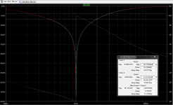
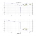
Well, to give it a push, here are the simulated and measured transfer functions of the variable (990 - 1010Hz) version of this filter, set at approx. 1kHz.
The measurement was made by feeding band-limited (20Hz to 20kHz) white noise signal from my B&K 1405 Noise Generator, and acquiring a long record of both the filter input and output with an audio card in 24/48 mode. The transfer function was then calculated in Matlab over a signal length of 500 seconds. The goal was to estimate the attenuation of the higher harmonics (needed for the THD measurements), and compare them to the simulation results.
The agreement between the results is very good. If the measured filter insertion loss of -2.8dB is added to the simulated value at 2kHz, i.e. -10.8 +(-2.8) = -13.6, the difference between the measurement and simulation is only 0.6dB, which is not bad given the modesty of the measurement setup.
I wish you all success with the filter!
Regards,
Braca
Attachments
Thanks Alex for putting this together, much appreciated.
As per Frex's question, if anyone is looking for Mini-MELF resistors for the Low Noise Amplifier, particularly in the EU, some values are in-stock at Farnell and others can be sourced on eBay (#311639973034). I've ordered a number of values from the eBay source, likely more than I'll ever need, so if anyone is stuck with particular values for the LNA I may be able to help. Please PM me.
As per Frex's question, if anyone is looking for Mini-MELF resistors for the Low Noise Amplifier, particularly in the EU, some values are in-stock at Farnell and others can be sourced on eBay (#311639973034). I've ordered a number of values from the eBay source, likely more than I'll ever need, so if anyone is stuck with particular values for the LNA I may be able to help. Please PM me.
In the last couple of years since the group buy has anyone characterized in more detail the distortion levels of this notch filter?
I ask since I am trying to more accurately measure ES9038Q2M, E-MU 1616m and Digidesign (modified) 003 rack performance with notch filters. So I am trying to find a notch filter design with quantified distortion performance of the notch filter and specific series and part numbers for the resistors and capacitors used to achieve that distortion performance.
I ask since I am trying to more accurately measure ES9038Q2M, E-MU 1616m and Digidesign (modified) 003 rack performance with notch filters. So I am trying to find a notch filter design with quantified distortion performance of the notch filter and specific series and part numbers for the resistors and capacitors used to achieve that distortion performance.
Last edited:
I've built three such filters, and the distortion of all of them was not measurable by the equipment I possess (Victor's oscillator, Groner's or Wurcer's LNA, a modded MOTU Audio Express interface).
I can post the construction details, but need some time to get organized.
Regards,
Braca
I can post the construction details, but need some time to get organized.
Regards,
Braca
Ok, here are the capacitor data.
The filter I'm currently using has a nominal notch frequency of 1kHz and is based on a capacitance of 100nF. Each leg is composed of ten 1206 ceramic NP0/C0G capacitors, nine of which have a capacity of 10nF, and the tenth one is trimmed such that each leg has nearly the same capacity.
I bought 50 capacitors (TDK CGA5L4C0G2J103J160AA) with a tolerance of 5% (1% caps are very expensive), measured the capacity of each of them and made three groups. The first group has ten caps and the other two nine caps each and must be trimmed such that their respective capacities are as close as possible to the first group value. This is achieved by finding a combination of the tenth capacitor and one of two smaller caps soldered "piggy back" onto the other ones.
The exact value of the capacitance is not important, but the matching of the three legs is critical: a deviation of 0,5% in a single leg reduces the notch depth by 30dB or more (my build achieves a notch depth of at least -100dB).
I hope the above description makes some sense.
Regards,
Braca
- Home
- Group Buys
- PCB for Samuel Groner's low distortion passive notch filter