Nah, cap only introduces low order harmonic distortion, no big deal, a choke is always cheaper and easier to make than a trafo.
The real nasties are the high order distortions. These come from crossover and active devices with exponential transfer functions.
I've done plenty of amps using coupling caps. Their ill effects are much exaggerated, they really are. A bit of judicious bypassing and they sound fantastic.
Cheers,
Hugh
Something old...
It was nice to see this thread. I bought a Twin Towers from Pathos at CES in 2000. I have heard a lot of stuff in the last 13 years, but that amplifier remains the best I have ever heard. (It did receive a few mods to sound its best.) That being said, many things were/are difficult to deal with. It's really heavy at over 100 lbs. Normally this isn't a big deal, but it isn't reliable, so it goes to be repaired often. It runs too hot to use in the Summer but does an excellent job of heating the house in the Winter. I sold the amp many years ago and a friend deals with all of the aforementioned issues along with the excellent sonics. Another of our friends struggles to keep it reliable.
Best to anyone that can build an improved and more reliable version of their wonderful sounding amplifier,
Chris
Hi everyone,
I'm currently re-building a diy version of the pathos tt amp. I have a lot of problems with the output stage and the biasing actually.
I use three irfp240 in parallel with 0.22r source resistance. Even with matched mosfets, the current sharing is not great, one of them almost always take 50% more current.
The other problem is thermal runaway, when I bias them with 2a at most, it seems ok but if I increase the bias (should be around 3amps), the current doesn't stop and one of the mosfets blows.
I thought about using some vbe multiplier to bias and provide thermal feedback or use lateral mosfets instead, but I can't decide on what to use to keep the good sonics of the unit.
I think that's the main reason of the unreliability of the pathos tt.
That means that mosfets are not matched (for a given current), you could also try a little higher source resistance, about 0.47 Ohms.
Try to use NTC/resistor combination from mosfets gates to ground for thermal compensation like Nelson in his F5 amp, it should do the job but you have to experiment with resistance valuses...
BTW 10K for gate stoppers it`s a bit funny value and I don`t think ECC83 is a way to go, but it`s a matter of taste")
Try to use NTC/resistor combination from mosfets gates to ground for thermal compensation like Nelson in his F5 amp, it should do the job but you have to experiment with resistance valuses...
BTW 10K for gate stoppers it`s a bit funny value and I don`t think ECC83 is a way to go, but it`s a matter of taste
I think I have some other issues at work with this thing.
There are three mosfets in line on a pcb mounted on the heatsink. Psu comes by the bottom. Each mosfet has a 2.2k gate stopper resistor (I will reduce the value later) and a 0.22R source resistor.
I power the thing from a lab supply.
If I set the psu at 10vdc and increase the bias until around 3 Amps, I get a near perfect match (0.230, 0.238, 0.224 measured across the .22R). When I increase the supply, the middle mosfets starts to draw more current.
At 20vdc, i get 0.221, 0.260, 0.212v across the 0.22R and the middle mosfet blew at 35vdc.
I run the same test with the two survivors mosfets, they share the current perfectly even at 35vdc (and 2A total bias).
The blown mosfet has short D-S and short G-S or G-D. What can cause this ? overcurrent, overvoltage, overtemperature, etc ?
I used two 12v zeners back to back from gate-source on each mosfet.
If I replace the middle mosfet by another one, matched with the others two, it's always the middle one that draw more current.
Hello,
I tried replacing the vertical irfp240 by buz900dp and that's a great success. I removed the .22R source resistor and place them in the drain for current measure. The current sharing is almost perfect, without matching.
The current decreases slowly as the thing heats up and then rest at some value.
No problem with the quiescent current of 3A and no mosfets blown.
I think the loss of transconductance will get somewhat balanced by the source resistor removal. I also changed the gate resistors to 470R.
Would someone have the PSU schematic of the pathos, especially for the +300v supply.
I want to try a simple capacitance multiplier with something like 1.8k - 22uF but I'm worried the resistor won't resist the charging current of the capacitor ?
Maybe there is some thermal-machanic reason why it is always the middel MOSFET that goes. Check, double-check and recheck mounting and isolation-disc.
The BUZ...isn't it a lateral? ...because they dont have thermal run-away, so this one is failsafe in your test-circuit, but you might still have the thermal-mechanical failure.
The BUZ...isn't it a lateral? ...because they dont have thermal run-away, so this one is failsafe in your test-circuit, but you might still have the thermal-mechanical failure.
I can't say about the thermal problem. I already checked the mounting many times and didn't found anything wrong. Maybe using verticals without thermal compensation is just insane, if you run them hot. Positive tempco does no good for current sharing either.
Yes the buz is a dual package version of 2sk1058 and is a lateral mosfet. Less gate threshold, less transconductance and ir has a 0 tempco around 100mA, negative for more current. This does help a lot for current sharing. Maybe the 250W rated power of the buz900 helps too.
Anyone for the tube psu schematic ?
Hi Softpack,
Can you please confirm R12 - 1k Ohm from the second part of service manual (Sovtek modification) because I think that 1k Ohm from grid to gnd is not logical? From technical specification of the Pathos the input impedance is 100k.
Any help is welcome
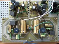
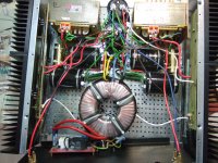
Here is some pics from my Pathos
Can you please confirm R12 - 1k Ohm from the second part of service manual (Sovtek modification) because I think that 1k Ohm from grid to gnd is not logical? From technical specification of the Pathos the input impedance is 100k.
Any help is welcome
Here is some pics from my Pathos
Attachments
I think I have some other issues at work with this thing.
There are three mosfets in line on a pcb mounted on the heatsink.
When I increase the supply, the middle mosfets starts to draw more current.
If I replace the middle mosfet by another one, matched with the others two, it's always the middle one that draw more current.
Apolon 34
The mosfet in the middle of the row, will always get hotter (assuming a planar common heat sink). Either place it below the other 2, or add metal and fins where this middle mosfet is attached.
Regards
George
Hi,
The heatsink was in vertical implantation. The upper one should be the hotter ?
anyway I had big thermal problems with this implementation. There is no thermal compensation on the schematic and maybe the heatsink-mosfet junction is just to short to ensure good thermal dissipation.
I solved the problem by using lateral mosfets, without source resistor.
Hi Apolon34,
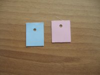
If you use irfp240 use one pair 15V zeners from gate to source common for all mosfets. R13 - 270k in service manual should be around 130k. Unplug preamplifier section from amplifier section. The mosfets should be very very tight connected with heatsink. Use pink pads like this on the picture not grey. With grey pads the temp over middle leg close to the case of the mosfets go over 100'C. Adjust voltage over choke to be 2.5V not more because at start with preamplifier section connected the voltage over choke will go to 5V !!!! for short. Otherwise you should build this section from service manual with delay relay.
Regards
Attachments
Hi,
I already noted the gate drive voltage rising at preamp start-up. I corrected the problem a bit by reducing the impedance of the resistor bridge that set-up the idle current. Bump is now much smaller.
I also now use a startup sequence controlled by a uC. Tube heating on for about 1 minute, then H.T then 10 seconds later the +38v for the mosfets.
I did effectively use the grey pads with thermal paste. I don't think using blue or red ones can alone solve all the problems of the amplifier, but maybe I'm wrong.
The more important flaw is long term temp runaway I think. Since it has positive tempco, it can never stop heating without a compensation bias circuit.
Voltage over choke is around 3v (3Amp idle, 1ohm dcr)
here is the new URL:
Klasse A Endstufe für Audiofrequenzverstärkung. - Dokument EP0653836
close by
http://www.pat2pdf.org/patents/pat5498997.pdf
This is an advantage in opposite to an additional CCS. What is the best choise for a choke coil? Are certainly main transformers (toroidal versions) also suited?Doing some more digging on this, I unearthed a review of the
Pathos Twin Towers amp by Dan Sweeny in Issue 116 (Feb '99)
of The Absolute Sound. In a sidebar on INPOL theory, he explains:
"Under no-signal conditions, the choke allows direct current to
flow unimpeded from the positive supply to ground [while] the
parallel capacitor ... provides additional energy storage while
equalizing the current draw for either half of the wave cycle, i.e.,
when the [output] MOSFET is sourcing or sinking current ...
"Impedances are set so that the total series impedance of the
capacitor plus the loudspeaker circuit is somewhat higher than
the impedance to ground; therefore current through the output
transistor never varies appreciably even though the internal
impedance of the MOSFET drops with increasing signal voltage."
In an effort to see if this could possibly be true, I quickly modeled
the INPOL output stage in Electronic Workbench. In this model at
least, the current through the MOSFET does vary by about 2:1 at
full output, just as it would with a constant current source load.
This appears to negate the claim of constant current operation.
This kind of choke loading does offer the benefit of cutting the
idle dissipation of the output stage in half when compared to a
CCS loading, as there is no need for a corresponding negative
power supply rail.
Last edited:
- Status
- This old topic is closed. If you want to reopen this topic, contact a moderator using the "Report Post" button.
- Home
- Amplifiers
- Solid State
- Pathos Amplifiers