That's not what it's used for. It's a special case of the sealed enclosure and the capacitor is part of the principle. It's main advantage is reducing the needed volume. The driver is fitted in a 'too small' enclosure with a Qt of ~1,1 - 1,2 (which is usually avoided). At the resonance the capacitor interacts with the hunch because of the high impedance at that frequency, equalizes the hunch, below the resonance the inductance is lower and the filter behaves different, because of the dropping impedance, which means the low end is actually extended, the level is higher and goes deeper than the normal sealed enclosure. The downside is the drop off flange is then steeper (12dB instead of 6dB of a normal sealed enclosure) but that is also a plus because it then reduces also the excursion.Why high-pass when I can go lower? There's no need for caps - All the caps I need are back there in the PSU!
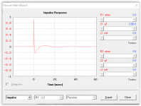
That's not the same because it isn't in the resonant system (speaker), that means you still get the long decay time and worse impulse response. And such a steep filter cause then exactly what you wanted to avoid - don't forget, every additional order increases the group delay!Besides, I have some decent Parametric EQ in my laptop from where I can apply an 8th order high-pass @ 30 Hz, which is much better than the one shown in the graphs.
It's a special case of the sealed enclosure and the capacitor is part of the principle.
Oh, so that's different from a normal first order filter! Good point!
that means you still get the long decay time and worse impulse response. And such a steep filter cause then exactly what you wanted to avoid - don't forget, every additional order increases the group delay!
I agree with the decay time but why the impulse response? The EQ is not going to increase the system's mechanical loss, IMHO.
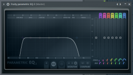
And for the EQ, does it still increase the group delay if it uses more complicated DSP? If you look at the attached photo you'll notice that It features a step-like filter that's like more than 36dB/octave and doesn't seem like a normal EQ approach. In the photo you'll see the normal 8th order ( the high shelf ) vs. the step 8th order ( the low shelf ). It's actually part of a professional mastering program ( FL studio ) that I have.
And by the way, does the capacitor trick decrease the excursion in the resonance region too or it only effects on the low lows? I guess I have some problem there; the excursion at highest levels exceeds the Xmax a little bit.
PS: How do I calculate the capacitor value? I couldn't find it in the filters section in winISD.
PPS: Does this capacitor work fine with the class-D amp? I've heard some caps like piezos show problems when used with class-D amps. Interference with the output stage LC's?
The amp module is this:
https://www.amazon.com/XINY-TPA3118-Digital-Amplifier-Module/dp/B01EWB48NC
Regards, Ali.
Attachments
Last edited:
Hi 4392Viper,
You did measure the Dd midpoint-to-midpoint on the surround for the T/S parameters from Post #37? Assuming all went correctly this time, the T/S indicate that this driver is for an infinite baffle, sadly it does not have enough Xmax to be very useful. It's quite typical for inexpensive drivers of this size (which will be advertised w/ T/S parameters straight from the sales department).
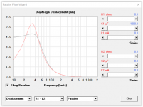
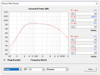
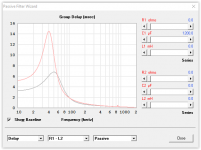
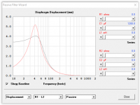
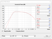
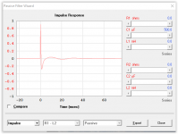
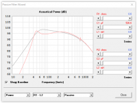
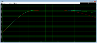
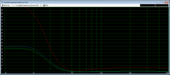
The series capacitor method ICG describes in Post #39 would require a non-polarized capacitor about 800 to 1000 uF; this can be simulated easily in Hornresp (from the SPL window click on - Tools - Filter Wizard...). I'll attach a sample using two 6.5" drivers mounted isobarically in a sealed enclosure w/ a series capacitor. Note that the displacement (red) now shows a bit of a peak v. the original (gray) sealed box low end shelf.
This is similar to something I have done in the past w/ a similar driver: mounted it isobarically (clam shell) at the end of a sealed box made from an 8"Dia. sonotube filled w/ polyfill. All this went under the backseat of a truck w/ its own amplifier, and worked surprisingly well; probably helped a lot by the cabin gain. Just don't expect hair raising levels. :=) I don't have any drawing from that project, so I'm attaching a sketch showing what memory tells me we did.
Regards,
You did measure the Dd midpoint-to-midpoint on the surround for the T/S parameters from Post #37? Assuming all went correctly this time, the T/S indicate that this driver is for an infinite baffle, sadly it does not have enough Xmax to be very useful. It's quite typical for inexpensive drivers of this size (which will be advertised w/ T/S parameters straight from the sales department).
The series capacitor method ICG describes in Post #39 would require a non-polarized capacitor about 800 to 1000 uF; this can be simulated easily in Hornresp (from the SPL window click on - Tools - Filter Wizard...). I'll attach a sample using two 6.5" drivers mounted isobarically in a sealed enclosure w/ a series capacitor. Note that the displacement (red) now shows a bit of a peak v. the original (gray) sealed box low end shelf.
This is similar to something I have done in the past w/ a similar driver: mounted it isobarically (clam shell) at the end of a sealed box made from an 8"Dia. sonotube filled w/ polyfill. All this went under the backseat of a truck w/ its own amplifier, and worked surprisingly well; probably helped a lot by the cabin gain. Just don't expect hair raising levels. :=) I don't have any drawing from that project, so I'm attaching a sketch showing what memory tells me we did.
Regards,
Attachments
It lowers the Qt, so you don't get the response of a Qt 1,2 speaker, you'll it of Qt 0,7-0,8 (depending on volume and capacitor value). And ofcourse a lot better impulse response than a ported system.I agree with the decay time but why the impulse response? The EQ is not going to increase the system's mechanical loss, IMHO.
Even if it's applied with a DSP, the result is the same, every additional filter adds 90° phase shift (-> group delay). The only way to avoid that is using FIR-Filter but that causes other issues, i.e. delays the signal (not an issue in your case I guess) and it introduces pre-ringing i.e..And for the EQ, does it still increase the group delay if it uses more complicated DSP? If you look at the attached photo you'll notice that It features a step-like filter that's like more than 36dB/octave and doesn't seem like a normal EQ approach. In the photo you'll see the normal 8th order ( the high shelf ) vs. the step 8th order ( the low shelf ). It's actually part of a professional mastering program ( FL studio ) that I have.
Anyway, very steep filters are often not the best solution, you have to compromise.
For a sealed enclosure spl is always excursion x piston area. So the excursion is reduced at the fb compared to the unfiltered version in the same volume. Below the fb it's excursion is higher (how else would you get more spl in the lower range?) until it's strongly reduced below the filter frequency. You don't get anything for free in physics.And by the way, does the capacitor trick decrease the excursion in the resonance region too or it only effects on the low lows? I guess I have some problem there; the excursion at highest levels exceeds the Xmax a little bit.
I don't use WinISD. You can ofcourse calculate it (don't have the formula at hand right now, sry) but I would just put in a few values and simulate it.PS: How do I calculate the capacitor value? I couldn't find it in the filters section in winISD.
tb46 already suggested a range, I would just simulate it with maybe 4 values
between 500 and 1500µF, also with both drivers on a separate channel and with both drivers in serial. You can also vary the volume, which changes the Qt, which in turn ofcourse changes the response. With the simulation you get faster to a visible result than calculating it and then realizing the response doens't look like you want it to be and do it over again and again.
Not only piezos can cause problems, the top end changes in level due to the interaction of the impedance with the output filters. Piezos cause ofcourse a lot more problems because of the extremely low impedance at very high frequencies. It's not an issue though, since you could easily introduce a serial resistor of a few ohms. But i disgress, sry. The capacitor of the sub is not an issue at all. Firstly, it's not a parallel capacitor, it's in series, thus don't lower the impedance. And secondly, it affects only the low end while the class D amps have the problems at the top end.PPS: Does this capacitor work fine with the class-D amp? I've heard some caps like piezos show problems when used with class-D amps. Interference with the output stage LC's?
Hi tb46,
I did it 1/3 to 1/3 - some even suggest to do it 1/4 to 1/4.
Compared to my other speakers right now, it's quite healthy on the excursion, though. I've seen much worse drivers!
Thank you for the simulation! I tried Hornresp and it's quite a large software; however, unfortunately the filter wizard doesn't work in my computer, showing the "Runtime Error 380". A search on the net and I found Mr McBean stating "It's a strange error"... There's no way in my computer to run the filter wizard IMHO.
Sorry, could you please kindly do me a favor and run another simulation with the following conditions:
2 woofers not isobaric wired in series to make an 8 ohm load.
A 18.5 lit. box
Cap values 500, 680 or 1000 uF
1.5" thick fiberglass lining ( I can go higher if it helps )
+ the group delay sheet
Thanks for your time.
Good Job! and thanks for the sketch.
Could you please explain more about Isobaric? I think it's not what I should pick as far as low distortion and bass extension is my goal - and no concern about high SPL.
Regards, Ali.
You did measure the Dd midpoint-to-midpoint on the surround for the T/S parameters from Post #37?
I did it 1/3 to 1/3 - some even suggest to do it 1/4 to 1/4.
Assuming all went correctly this time, the T/S indicate that this driver is for an infinite baffle, sadly it does not have enough Xmax to be very useful. It's quite typical for inexpensive drivers of this size (which will be advertised w/ T/S parameters straight from the sales department).
Compared to my other speakers right now, it's quite healthy on the excursion, though. I've seen much worse drivers!
The series capacitor method ...
Thank you for the simulation! I tried Hornresp and it's quite a large software; however, unfortunately the filter wizard doesn't work in my computer, showing the "Runtime Error 380". A search on the net and I found Mr McBean stating "It's a strange error"... There's no way in my computer to run the filter wizard IMHO.
Sorry, could you please kindly do me a favor and run another simulation with the following conditions:
2 woofers not isobaric wired in series to make an 8 ohm load.
A 18.5 lit. box
Cap values 500, 680 or 1000 uF
1.5" thick fiberglass lining ( I can go higher if it helps )
+ the group delay sheet
Thanks for your time.
... something I have done in the past...
Good Job! and thanks for the sketch.
Could you please explain more about Isobaric? I think it's not what I should pick as far as low distortion and bass extension is my goal - and no concern about high SPL.
Regards, Ali.
Last edited:
Hi ICG,
That's so good! I think the filter will save me from the over-excursion , thus the muddy bass. One question, though: Should I worry about the pi/2 of phase shift the cap causes in the signal?
Sorry for the cheap question, my bad.
So the problem is on the low impedance- I didn't know that. And yes, you're right. It's quite understandable now.
Regards, Ali.
It lowers the Qt, so you don't get the response of a Qt 1,2 speaker, you'll it of Qt 0,7-0,8 (depending on volume and capacitor value). And ofcourse a lot better impulse response than a ported system.
That's so good! I think the filter will save me from the over-excursion , thus the muddy bass. One question, though: Should I worry about the pi/2 of phase shift the cap causes in the signal?
Below the fb it's excursion is higher (how else would you get more spl in the lower range?)
Sorry for the cheap question, my bad.
Firstly, it's not a parallel capacitor, it's in series, thus don't lower the impedance. And secondly, it affects only the low end while the class D amps have the problems at the top end.
So the problem is on the low impedance- I didn't know that. And yes, you're right. It's quite understandable now.
Regards, Ali.
Hi 4392Viper,
Isobaric Subwoofer Design ? VUE Audiotechnik
Post #45: "...explain more about Isobaric?"
https://en.wikipedia.org/wiki/Isobaric_loudspeaker
That's a start, I found the reduction of required volume (1/2) to be quite correct, and the speakers seem to produce lower distortion, especially when mounted cone-to-cone as in my previous sketch. Also, search the diyaudio subwoofer forum for lots of information.
The best way to find out is by experimentation, you might just like isobaric(..k).
*******************
Post #45: "...could you please kindly do me a favor and run another simulation with the following conditions:..."
I'll attach what I have time for. I'm already working on projects for my "boss" at home. Post your problems w/ running Hornresp in the Hornresp thread, there are always people willing to help.
Regards,
Attachments
That's not entirely true. The outwards speaker takes up space too, so, unless you want it to stick out freely and non-protected, you have to extend the enclosure in some way. But even if you don't extend it, the outwards chassis enlarges the overall dimension in some way. So the actual volume of the whole box can't be exactly halved in praxis. That may not be neglected especally at small to very small enclosures since in such cases the additional % used up by the 2nd speaker might not make it worth, I mean, the 2nd speaker doesn't add anything to the spl after all.That's a start, I found the reduction of required volume (1/2) to be quite correct, and the speakers seem to produce lower distortion, especially when mounted cone-to-cone as in my previous sketch.
The best use is if you have cheap drivers which would require a large enclosure and probably got asymmetrical/nonlinear behaviour since most of these flaws are then cancelled out, it could make it cheaper and possibly equally good as using a better (more expensive) speaker.
It definitely helps.That's so good! I think the filter will save me from the over-excursion , thus the muddy bass.
") If it's the behaviour/response you want, depends mostly on your listening room and the placement of the subs though but you can vary the capacitor to adjust it.
If it's the behaviour/response you want, depends mostly on your listening room and the placement of the subs though but you can vary the capacitor to adjust it.One question, though: Should I worry about the pi/2 of phase shift the cap causes in the signal?
No, it's still less than the phase shift of a bassreflex enclosure.
Sorry for the cheap question, my bad.
No, not at all. If you are new to something, it's absolutely legitimit to ask such questions without thinking around too much corners. I mean, to apply less assumptions and simply ask prevents from hidden errors and building up faulty 'knowledge'. I'm just not in the best mood these days, maybe some things sounded different than they are ment.
Glad I could help in any way.So the problem is on the low impedance- I didn't know that. And yes, you're right. It's quite understandable now
Hi tb46, and thank you so much about the links.
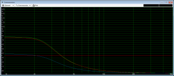
I can't thank you enough! That is one valuable piece of knowledge about caps. Based on the graphs you sent, I can now see the difference, especially that the impulse response improved with bigger caps, also the impulse "distortion" is moved down in the frequency. I can guess that the cap I need to compensate the 30 Hz "hump" in my excursion curve, and to extend my low-end FR is about 1500 uF to 3300 uF, which is pretty hard to find for the rated voltage, and, of course, pretty much expensive. However, I'll give the method a try whenever I can find a suitable cap. Can I use an array of series/parallel caps making up the same value instead of just one? Do the rules for DC apply for AC as well?
Ahh, "Boss"... Just hope he/she is not a difficult one.
---------
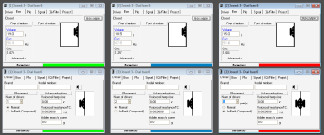
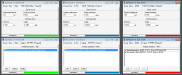
And for the Isobaric, I did some research and ran a simulation in winISD, which was quite shocking for me. Here are the details:
I chose 3 alignments to compare,
1- (Green) Single woofer in a 19 lit. sealed ................. 2 W
2- (Blue) Dual woofer in an 18.5 lit. sealed ............... 1 W each
3- (Red) Isobaric cone-to-cone in a 15 lit. sealed ..... 8 W (not sure)
The box volumes are the maximum allowed volumes due to "portability" issues. I applied the wattage needed to generate the same SPL, and the Linkwitz transform @ 27 Hz, Q = 0.9 for the three alignments to give the same FR curve (just for this case). Then, I compared the following:
Group delay was pretty much the same.
Cone excursion was half as much for the dual woofer, obviously.
Power load on the amp was not good, though. For every watt of "unEQ'd" power, I needed more than 100 W of "EQ'd" for the isobaric. I guess this was due to the low efficiency of the isobaric. Why is that?
I think The alignment is good for the occasions where big drivers are chosen and the only major concern is space. And, I think it's not my pick as I'm a little bit low on the power (Both amp power and drivers' input power).
Thanks again for your time,
Regards, Ali.
I'll attach what I have time for.
I can't thank you enough! That is one valuable piece of knowledge about caps. Based on the graphs you sent, I can now see the difference, especially that the impulse response improved with bigger caps, also the impulse "distortion" is moved down in the frequency. I can guess that the cap I need to compensate the 30 Hz "hump" in my excursion curve, and to extend my low-end FR is about 1500 uF to 3300 uF, which is pretty hard to find for the rated voltage, and, of course, pretty much expensive. However, I'll give the method a try whenever I can find a suitable cap. Can I use an array of series/parallel caps making up the same value instead of just one? Do the rules for DC apply for AC as well?
...for my "boss"...
Ahh, "Boss"... Just hope he/she is not a difficult one.
---------
And for the Isobaric, I did some research and ran a simulation in winISD, which was quite shocking for me. Here are the details:
I chose 3 alignments to compare,
1- (Green) Single woofer in a 19 lit. sealed ................. 2 W
2- (Blue) Dual woofer in an 18.5 lit. sealed ............... 1 W each
3- (Red) Isobaric cone-to-cone in a 15 lit. sealed ..... 8 W (not sure)
The box volumes are the maximum allowed volumes due to "portability" issues. I applied the wattage needed to generate the same SPL, and the Linkwitz transform @ 27 Hz, Q = 0.9 for the three alignments to give the same FR curve (just for this case). Then, I compared the following:
Group delay was pretty much the same.
Cone excursion was half as much for the dual woofer, obviously.
Power load on the amp was not good, though. For every watt of "unEQ'd" power, I needed more than 100 W of "EQ'd" for the isobaric. I guess this was due to the low efficiency of the isobaric. Why is that?
I think The alignment is good for the occasions where big drivers are chosen and the only major concern is space. And, I think it's not my pick as I'm a little bit low on the power (Both amp power and drivers' input power).
Thanks again for your time,
Regards, Ali.
Attachments
Last edited:
Hi ICG,
That's what I faced in the simulations. Even with isobaric, I actually couldn't get a Q lower than 1 because of the outer dimensions I'm stuck with.
Only if I could do something with the power requirements.
Hope your mood gets better soon! Take it easy!
Regards, Ali.
That's not entirely true.
That's what I faced in the simulations. Even with isobaric, I actually couldn't get a Q lower than 1 because of the outer dimensions I'm stuck with.
The best use is if you have cheap drivers which would require a large enclosure and probably got asymmetrical/nonlinear behaviour since most of these flaws are then cancelled out, it could make it cheaper and possibly equally good as using a better (more expensive) speaker.
Only if I could do something with the power requirements.
I'm just not in the best mood these days...
Hope your mood gets better soon!
Take it easy!Regards, Ali.
Technically, it only halves the Vas. Unless you have an already usable Qts and working enclosure (which just happens to be too big), it does not much for you in many cases.That's what I faced in the simulations. Even with isobaric, I actually couldn't get a Q lower than 1 because of the outer dimensions I'm stuck with.
The power isn't the problem, the excursion is.Only if I could do something with the power requirements.
Thank you very much. My uncle died meanwhile, so that didn't help my mood much.Hope your mood gets better soon!
It's not your fault (or anyone elses), I'm just soo sad.. Technically, it only halves the Vas.
AND, for a given power, reduces the SPL by a massive -9dB (according to winISD), eating up my whole 10dB headroom for EQ'ing.
The power isn't the problem, the excursion is.
You're quite right. Ran another couple of simulations in the meantime and, yes, excursion was the most severe problem. Taking the EQ up near an octave was of a little advantage, if any.
My uncle died meanwhile...
Really sorry to hear that. That must've been tough. You have my condolence.
Regards, Ali.
Last edited:
- Status
- This old topic is closed. If you want to reopen this topic, contact a moderator using the "Report Post" button.
- Home
- Loudspeakers
- Subwoofers
- Passive Radiator Compromises