mastertech said:Hi everyone how youre doin
choky may i ask what is the dcoffset of your circuit
cheers
below 100mV,from cold to hot-even with that prototype mess on pics
near 100mV at cold
near 000 hot
anyway-smaller than finished JLH

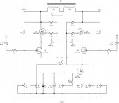
Very true. Beta min for a philips BD140-16 is 100. Good enuf for aI implement one resistor under CCS (Q2& Q3) ,to little ease life for Q2;
another solution was to place something like 2 pieces of BD140-16 back-to-back,but this looks more elegant solution, and little BCs just have more beta .....
CCS.
I like mounting two of these back to back, flat on PCB or Perf
board with an M3 screw. Isolated in between. Makes it nice and
strurdy. But that's just me.
Very true. And that's on of the appealing factors to me as well.... 45W per device
don't forget that these Alephs are commercial devices...and I resume that Papa Nelson made this decision with some thinkering and experience.......
These Aleph's are not easely ruined.
Slightly different pupose. Ever heard of a cooked antenna?ever heard a story about old school radio Hams -cooking 6L6 in bucket of oil,with quadruple max dissipation?...
(just kidding)
Nice circuit, gets good looks. Your circuit deserves that.... will be Oak too,placed on 4 studs in corners,with some 15mm clearance to sides...
Regards
rtirion said:
Nice circuit, gets good looks. Your circuit deserves that.
Regards
tnx...
small correction-it's Papa's circuit

I have never built Aleph yet because the circuit is farrrr complicated for me . . .  . . . Anyhow, your Babbelfish looks delicious . . .
As I finished my Krazy, with time I used my finger to examine the fish once again all the way carefully, wondering whether steaming or frying it could be better . . .
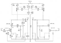
Umm . . . the current limit protection seems to be set with high value . . . why so high . . ?
The right side leg of LTP is sit on the top of the source resistor . . . to save one resistor . . . ? . . .
What was yr thinking with these . . . ?
jh
. . . Anyhow, your Babbelfish looks delicious . . .As I finished my Krazy, with time I used my finger to examine the fish once again all the way carefully, wondering whether steaming or frying it could be better . . .
Umm . . . the current limit protection seems to be set with high value . . . why so high . . ?
The right side leg of LTP is sit on the top of the source resistor . . . to save one resistor . . . ?
. . .What was yr thinking with these . . . ?
jh
jh6you said:I have never built Aleph yet because the circuit is farrrr complicated for me . . .
As I finished my Krazy, with time I used my finger to examine the fish once again all the way carefully, wondering whether steaming or frying it could be better . . .
Umm . . . the current limit protection seems to be set with high value . . . why so high . . ?
The right side leg of LTP is sit on the top of the source resistor . . . to save one resistor . . . ?
What was yr thinking with these . . . ?
jh
hiya my yinyang boy
Aleph's complication is in fact just matter of drawing.....especially when you draw just one output pair
hehe-then it's not complicatedjust take pen and the paper and start drawing block by block;
each part have his own role;
when you'll finish,nothing will be complicated.
.... current limit-just isn't tested in prototype ; when I'll have finall pcb ,then siggene ,dummy load and CRO will tell everything;
right side leg of LTP......... sorta folded cascode,if I'm right........
jh6you said:Tanks understood . . . sorta folded cascode . . .
Hmm . . . now I start to examine inside of Babbalfish, to learn whether even its liver is eatable . . .
jh
feel free to ask ...
I'll learn more if I try to answer what I don't know.......

Samuel Jayaraj said:Choky, have you already mentioned somewhere about how your version of the Pass JFET amplifier sounds?
Thanks, even if you do repeat it.
http://www.diyaudio.com/forums/showthread.php?postid=845666#post845666
wuffwaff said:Hi,
nice to hear that the Aleph-J is working! Just one question:
why the two source resistors (43R)? Wouldn´t it work without them?
William
probably it will work;
in fact-for sure;
it's just playing on safe side....
Alain,
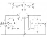
Can you please describe what's going on with the circuitry above your outputs (C4, Q3 - Q6, etc.)? I'm not very knowledgeable about this stuff. If you can provide a link to a description that would work, too.
By the way, after studying the Zen articles, I did a cut and paste job to come up with the attached circuit. But I do not have the skill to know if it would work or if I've created a frankenzen.
Regardless, your design eliminates the inductor coupling which, since I don't have large transformers laying around, might be cheaper. Are there other benefits to your approach? Is it more efficient?
Thanks.
Paul Ebert
Paul,
I started in Post #306 of this thread...
continuing on Post #410
with some ideas... :smilie(':bs:')
And it covers the points 2, 3, 4, 5, 5bis, of my note {from Post #306}
I didn't yet receive the JFet's from Grey, but I think they are on their way...
So you'll have to wait till then, I have no idea if this will work, but it's worse a try!
If Grey has a moment, he sure could tell us about-it!
It's pure vision, I have no simulator at home Mac OS X 10.2 !
Regards.
Alain.
Choky, I have found locally the following FETs: J164, J165, J176, J310.
Of these, the J310 appears to be the most likely part to replace the J109 differential pair in your JFET Aleph. Do you think I need to change any values of parts or current settings?
I have with me two torroidal transformers. They are rated at 180VA and have 25-0-25 volt windings.
What if I used a capacitance multiplier with IRFP260s and used either IRFP260 or IRFP460 for the outputs of the amps? Would this be better or is IRFP250/150 a better part?
I would like to use this only for mid/high frequency application driving Fostex 168EZ in Open Baffle. Low frequency duties would be taken care of by 10"x2 or 15"/18" x1 driven by Stochino amps whose bass I love.
Any advice?
- Status
- This old topic is closed. If you want to reopen this topic, contact a moderator using the "Report Post" button.
- Home
- Amplifiers
- Pass Labs
- Pass JFET Power Amplifier