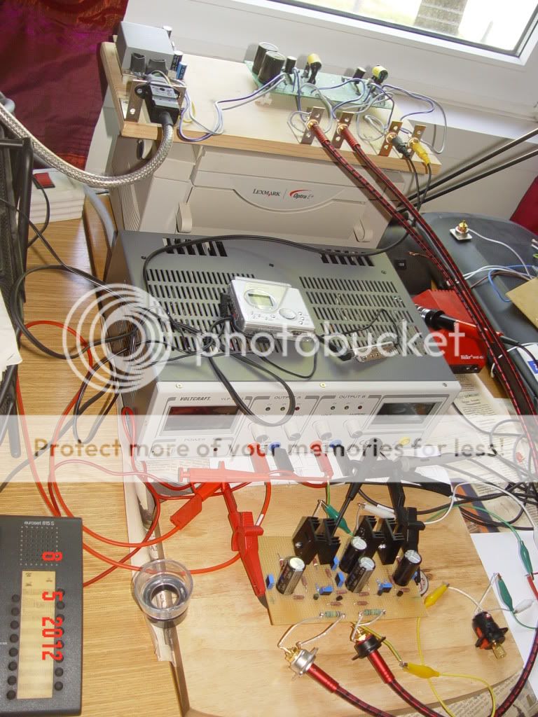
Just to avoid any missunderstandigs ... When I said that I removed input and output resistors I meant: R1 and R12. They are there mostly to protect the circuit from possible oscillations.
In the final version I will also remove R2 (now I have it) because I will have a buffer in front of this BA3 circuit. This is going to be Pass B1 buffer, which already has a resistor to ground at its output.
The reason for removing R12 is mainly motivated with the wish to keep the output impedance as low as possible. The fact that this circuit is going to be used as a headphone amplifier makes the output impedance an issue.
If anyone accidentally or deliberately hot plugs an interconnect, then both sides of the unplugged need the ground referencing resistor.
Those grounding resistors become redundant* when the interconnect is plugged at both ends.
redundant*, if the value is chosen high enough to have little effect on input and output impedances and yet low enough to divert leakage to ground leaving little DC at the hot terminal when unplugged.
Those grounding resistors become redundant* when the interconnect is plugged at both ends.
redundant*, if the value is chosen high enough to have little effect on input and output impedances and yet low enough to divert leakage to ground leaving little DC at the hot terminal when unplugged.
If anyone accidentally or deliberately hot plugs an interconnect, then both sides of the unplugged need the ground referencing resistor.
Those grounding resistors become redundant* when the interconnect is plugged at both ends.
redundant*, if the value is chosen high enough to have little effect on input and output impedances and yet low enough to divert leakage to ground leaving little DC at the hot terminal when unplugged.
Absolutely true ...
Does that agreement confirm you are not about to remove the ground referencing resistors !!!!
Probably I will because I will have them on a previous board, which is B1. I will simply connect with wires the outputs of B1 to the inputs od BA3. In that way, I will get the ground from B1.
For better understanding: I will have remote volume board - B1 buffer - BA3 circuit - relay to switch the output either to RCA Out or to Headphone out ... all in one enclosure with separate PSUs for all these parts. I am thinking at this moment that I have to connect the grounds of volume remote control, B1 and BA3. Any suggestions for the implementation of these ground connections are welcome though ...
Then you are not agreeing.
Where do you see the problem ? Why do you think that I should put in parallel to 220K at the output of B1 another 47K at the input of BA3 ? They will be directly connected.
My thinking is that it does make sense to keep these BA3 input resistors in case if the grounds are not connected - which also has some advantages, mainly because the eventual ground garbage will not be transported to BA3.
- Status
- This old topic is closed. If you want to reopen this topic, contact a moderator using the "Report Post" button.
- Home
- Amplifiers
- Pass Labs
- Pass Headphone Amp
