^ I wasn't the one that brought it up... I simply asked him for clarity.
You... on the other hand... seemed to want to continue to discuss it... and clearly did not understand.
Me... I'd avoid having the pad touch the bolt in all situations (personally, I didn't use the pads at all), but that's my choice.
Cheers.
You... on the other hand... seemed to want to continue to discuss it... and clearly did not understand.
Me... I'd avoid having the pad touch the bolt in all situations (personally, I didn't use the pads at all), but that's my choice.
Cheers.


Surprisingly, I've been using those transistor heatsink clips for the power transistor packages instead of screws/tapped holes for awhile now and found them to be rather convenient especially for power supply and amp load testing, etc. There a wide variety of them to suit all sorts of options ...
Do you have an example of which ones you use?Surprisingly, I've been using those transistor heatsink clips for the power transistor packages instead of screws/tapped holes for awhile now and found them to be rather convenient especially for power supply and amp load testing, etc. There a wide variety of them to suit all sorts of options ...
Here are some. The MAX08NG is for TO-247.
https://www.mouser.com/c/thermal-management/heat-sinks/?m=Aavid&series=Clips
https://www.mouser.com/c/thermal-management/heat-sinks/?m=Aavid&series=Clips
Hey TonyEE,
Maybe it is unfortunate that you missed the window to get the special F5m boards. Luckily, it is very possible to build an F5m that sounds really great using standard F5 PCBs plus the Universal PS board. We have seen how it can be done in this thread. Pretty cheap too.
As usual the big ticket items are the chassis and power transformer. One you have decided which ones to use, read the F5m article to get the BOM. Order the parts you need and enjoy a custom build.
Hey TonyEE,
Maybe it is unfortunate that you missed the window to get the special F5m boards. Luckily, it is very possible to build an F5m that sounds really great using standard F5 PCBs plus the Universal PS board. We have seen how it can be done in this thread. Pretty cheap too.
As usual the big ticket items are the chassis and power transformer. One you have decided which ones to use, read the F5m article to get the BOM. Order the parts you need and enjoy a custom build.
I already have an F5.
I'd rather wait for the real F5m boards.
Nonetheless, thanks for the thought.
Yes, you could do that. It would be wise to test the result with an ohmmeter.So with these insulators not insulating, could one simply install the output devices without a insulator onto an anodized surface with goop? I suppose that would be pushing our luck...
On the point of the bolt talking to the insulator, I checked that and its a pretty resistive result.
Nevertheless, anyone who feels nervous about this should simply request the offered replacements.
They are in transit, and will be here shortly.

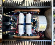
As written in the F5m kit thread, I recently rebuilt my PSU to lower the rail voltage. Mine are now running at 26V, but I may tweak them again to try a slightly higher setting. Bias current is presently set at 1.53A, but that is also under revision. The amp sounds really good at this operating point, and I am enjoying little tweaks here and there to see how the sound is affected. A point I made in the other thread is that I am not chasing more power delivery to my speakers, but trying different ways of biasing the output FETs to see where their sweet spot lies for the best sound.
The FQA and IXTQ parts that I am using are similar to what is being discussed for the ZD25 "Holy Grail" output stage. They are different from the usual parts found in the various Papa amps that we love to build. In particular, they are rated to dissipate a little more power, and exhibit higher transconductance at higher Vds. These attributes make it worthwhile to do some experimentation.
One of the more notable things I have found is that the F5m performs better with higher amounts of capacitance in the PSU. I built the new PSU with 18,000 uF caps and then added 24,000 uF onto the output terminals, where the boards and speaker returns are connected. This proved to be an essential addition, in that it improved imaging and instrumental details pretty much across the board. I recommend this for any builds where there is enough room, or even choosing a different internal layout to make the necessary room.
Attachments
Hi NelsonCompletion Kit Alert,
Thanks to member Oreo382 we have discovered that the insulator pads for the output transistors are
not very insulator:
https://www.diyaudio.com/community/...dio-store-feedback-thread.221467/post-7635232
Of the 100 kits that have shipped, I am happy to mail different insulators to send to anyone with bare metal sinks.
You can send your address to nelson@passlabs.com
I sent my address for replacement insulating Pads a=two weeks back but did nit get anything yet?
hope it is in your radar
kannan
Time has come to end the tweaks to this fine amplifier.
Bias current sits at 1.50 Amps and DC offset is within 10mV. This circuit seems at its best when DC offset is kept to a minimum. Rail voltages are a hair over 26V.
The sound is lovely, both smooth and detailed. Soundstaging is precise with excellent fill from side to side and top to bottom.
The FQA28N15 and ITXQ26P20P make an excellent pair of output devices.
Are you sure? For many years I read complains on different DIY forums that he sell fake components.Ebay seller POLIDA is a source for genuine parts
Just google "ebay polida fake".
- Home
- Amplifiers
- Pass Labs
- Pass F5m