I have been studying for a couple of days the variety of PS Filter caps to use in my Pass design Adcom GFA-555 amplifier. For one it seems there are not a huge variety of 15000uf 100v caps out there to be had. I have scoured the earth and am leaning toward a Vishay PHR-ST type. $38 a pop.
Max ESR 16 Mohm @ 100hz.
Rated ripple current @ 100hz = 12.3
What have others used for this amp design?
Max ESR 16 Mohm @ 100hz.
Rated ripple current @ 100hz = 12.3
What have others used for this amp design?
I have been selling the 22,000Uf 100V caps as replacements
http://www.apexjr.com/images/AdcomCap.jpg
There $23.95ea and have 23 left in stock
Steve @ Apex Jr
http://www.apexjr.com/images/AdcomCap.jpg
There $23.95ea and have 23 left in stock
Steve @ Apex Jr
For safety. If the rail fuses are blown, high voltage can sit on those caps
long enough to zap a technician.

Thank you sir for the kind advice, it is very appreciated. I am trying to quieten the big cat so no blown rail fuses. I will gator clip a 100K 2W resistor between them for awhile and leave it there as I work ok.
Happy Holidays and thanks again.
if you are sure in your work - just put foot on the gas
if you have doubts in your work , use bulb safety thingie
Looks like I will just straighten my knee on the gas pedal then...........
Good sound advice.Rather than just switch on the amp after working on the PS, you should remove the rail fuses between the PS and amp circuit, and check the PS alone. This way you'll only blow the PS and not the amp if something's wrong.

Ok. The filter caps are in but I have a few questions. The old filter caps look to be wired in series with no polarity showing on the caps. How do I complete the installation of the new caps observing correct polarity? The amp also has one wire, left channel side, which goes to the power on led. Two others on the right side go to the distortion lights. Do these go on the negative or positive terminals of the new caps?
Again if the old caps had polarity markings on them I would replace with no problems. I am just confused how the new caps should go in.
Thanks and Happy Holidays.
Again if the old caps had polarity markings on them I would replace with no problems. I am just confused how the new caps should go in.
Thanks and Happy Holidays.
AFAIK all polarized caps have polarity marked on them one way or another ... a stripe or a dot square lead or something. if all else fails remove rail fuses and ck for polarity on board with out caps installed. dim bulb and variac can be your friend if all else fails.
good luck my friend,
Elwood
good luck my friend,
Elwood
I would imagine the polarity designations on these caps were hidden by a custom wrap put on them by Adcom. Really nothing there.View the attachment to see how I have them wired at this time which I think is wrong. I believe I need to flip the first cap up in the front of the unit 180 degrees and wire them in series.
I thought my work was correct. I pulled the rail fuses and hit the on switch which blowed the main 10amp fuse. Hopefully nothing has been hit hard and the fuse + pulling the rail fuses saved any damage.
I thought my work was correct. I pulled the rail fuses and hit the on switch which blowed the main 10amp fuse. Hopefully nothing has been hit hard and the fuse + pulling the rail fuses saved any damage.
AFAIK all polarized caps have polarity marked on them one way or another ... a stripe or a dot square lead or something. if all else fails remove rail fuses and ck for polarity on board with out caps installed. dim bulb and variac can be your friend if all else fails.
good luck my friend,
Elwood
Attachments
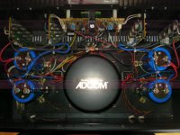
I guess you realize that the cap at the lower left is not connected.
Yes sir! Glad you saw that.....makes me know that you are sincerely looking at the picture. I disconnected the cap, was going to rotate it to get it connected in series, and then stopped until I could get this sorted out.
Thanks for the response.
Ok so now I have the power caps wired properly in series and read 80v at each rail. I have yet to replace the rail fuses as I would like to hear back from anyone who might have advice on what to check next before I do that.
My concern is that I have damaged something in the process of having the caps wired incorrectly.
Should I get an accurate offset voltage reading at this time with rail fuses pulled?
My concern is that I have damaged something in the process of having the caps wired incorrectly.
Should I get an accurate offset voltage reading at this time with rail fuses pulled?
Last edited:
Dont know if this will be of any assistance but I just got a GFA-555 Friday so here are a few pictures of the interior as it came to me.....
http://i167.photobucket.com/albums/u156/delecoy/DSC03572.jpg
http://i167.photobucket.com/albums/u156/delecoy/DSC03566.jpg
http://i167.photobucket.com/albums/u156/delecoy/DSC03565.jpg
http://i167.photobucket.com/albums/u156/delecoy/DSC03572.jpg
http://i167.photobucket.com/albums/u156/delecoy/DSC03566.jpg
http://i167.photobucket.com/albums/u156/delecoy/DSC03565.jpg
Thank you for responding. That is a schematic for the 555II which was a later version and much different. I have a schematic but am not adept at reading it as I should be.
I got the amp running now. The offset voltages are all good and everything is sounding nice. I will run it for the next few days and see what changes replacing the 25 year old filter capacitors make.
One day I will hit this forum with a amp build rather than a trouble question. All in time. Thank you for your help.
will this help ?
- Status
- This old topic is closed. If you want to reopen this topic, contact a moderator using the "Report Post" button.
- Home
- Amplifiers
- Pass Labs
- Pass Design Adcom - Filter Cap Problem