I'm getting +/-45 VDC out of the original transfos with 4 Philips 8200uF 100 volts caps.
I'm using exactly (hope so...) the enclosed schematics at the exception of the IRF130/9230 which are replaced by 2SK135/J50.
...And it sounds damned good!!!! In Tracer 100 speakers...
And I did not forget to swap drain and source pins.
I'm using exactly (hope so...) the enclosed schematics at the exception of the IRF130/9230 which are replaced by 2SK135/J50.
...And it sounds damned good!!!! In Tracer 100 speakers...
And I did not forget to swap drain and source pins.
Attachments
Last edited:
...
I'm using exactly (hope so...) the enclosed schematics at the exception of the IRF130/9230 which are replaced by 2SK135/J50.
...
To lower the bias current, you'll have to lower the value of R14 to 4k7 (or to 5k by adding another 10k in parallel to R14).
If you want to take out the Vbe multiplier circuit (Q4, R14, R17) and use a single resistor to bias the output stage just put a 1k or 2k multi-turn pot in parallel with C5 instead. Don't forget to set that pot to 0 Ohm before turning the amp on.
Also, check the current through Q3 (should be about 5 mA) by measuring the voltage across R13. If that's so, you'll have the output stage bias at 150-200 mA with pot set at 400-500 Ohms.
I put a 10k in parallel of R14. Worked fine of 1 side; lowering the value of the pot in parallel of R15 got me a bias of 150ma measured at the + rail output of the diode bridge. And I had more range if needed.
On the other side, a strange thing happened; at first, the current lowered to 250ma but when lowering the value of R15 & the pot, current increased instead of getting lower...??? I guess I have something wrong somewhere in this channel... I'll dig in it.
Didn't have time to look at the sinewave, neither the clipping.
Problem!!!
Oups problem. I've decided to look a bit deeper in this biasing problem and end up with a channel non working anymore... I get the + rail at output.
Didn't change nada... Just disconnected the + rail between bridge and + feed of the board to measure current but no current on the channel; verified and found +45 at +output...?
Start verifying the FETs and don't know if this is supposedly normal but even without gate voltage there is current going through the FET between drain & source. Checked the other J50 I have and same thing. Checked a IRF130 and same again so it may be normal.
Do I have to "ground" the gate to close the junction? I've verified with ohm meter in diode check and get .330 on the good side and open in backward. So no short there.
I'm used to check Mosfet with a 1K pot, tap on the gate and both sides on the drain & source. + at drain for N channel and gnd on drain for P channel. Is this OK? I've measured the K135 to close junction with .5VDC but the J50 is always closed...
The other channel is fine and now running at 190 ma with the addition of 10K in parallel of R14. I'm kind of afraid to remove anything from there... I could also just swing the board reverve as it's miror but if I've shorted something I don't want to do the same on the other channel...
I've verified all the B139/B140 and they are all good none shorted.
What's wrong?
HAHA .... just noticed the test setup I'm using for FETs comes from: https://www.passdiy.com/pdf/mos.pdf
Last edited:
Forget last post
Can't edit it my last post anymore, too late.
I was stupidly measuring the FET backward... Don't do too many things at the same time... Both are fine. The K135 starts conducting around.5V and the J50 around .2V.
I'll continue measuring voltages across... Will see where I'll get. I know I have the +45 all over on this channel, up to the N FET gate.
...
HAHA .... just noticed the test setup I'm using for FETs comes from: https://www.passdiy.com/pdf/mos.pdf
That's a fine article and you should read it carefully in order to understand how these devices operate.
For a quick check use the attached schematic. If MOSFETs are OK you'll have about 9V across the 100R resistors which means that they conduct current as they should. Be careful with pinouts and polarities.
Be careful not to burn the MOSFETs. They can't take more than 15V between Source and Gate...... I have the +45 all over on this channel, up to the N FET gate.
Attachments
GOT IT!
No Idea why, I've verified everything, I replaced the 10K parallel of R14 (I removed for troubleshooting this 45 V O/P) and everything is on spot...
I then replaced both R14 by a single 2.2K and I am now running at 150ma bias both sides and have room to increase or lower bias value. Is 2.2K OK ? Should I also replace R15 & 17 to have more equal values?
Problem probably was another of these "lunatic" goof...
Have a bit high voltage at output: 37ma on one side and 80 on the other. I'll try the other FETs I have to see if I can lower this value a bit more decent; under 50ma...
Thanks all for your help, specially Juma!! I understand a bit more this VBE thing.
I need to get back to my semi books. Left school some years ago and did a lot of electronics: troubleshooting systems & replacing modules & equipment. Never worked on discrete components. Never had to.
Well... couldn't be that fast...
Clipping is not too good... I get lower side to clip quite earlier then top side. I've tested in 8 ohms dummy loads. I can get to 20 volts RMS even but higher only gets me clipping the low side.
Does that mean 150 ma of bias current not enough? I remember having one amp with the lower K133/J48 and it was running pretty hot too after a while...
Should I replace R18 & R19 instead of R14? Or go with the single pot parallel of C5 ?
Dooooo Yes I did...
Problem is I like it so much I put it in my cabinet with the other stuff and cant get it out of there.. I like it too much !!! Warm like tubes and punch and details like a Bryston with a hughe 3D image. Can't ask for better....
I've bought some cct cards from a swedish guy here on DIY and am planning on building another one without any H-K stuff. I have 2 toroidal transfos from a burned SIMA amp, a bunch of PS audio gold 3300 uf 70 V caps ( 3 on each side on each channel ) some new 240 & 9240 FETs with some 1% metal film (I think?) resistors. Can it be better then this one? I'll see. I'm more then really satisfied with this one. Plenty of power, clean and detailed, image and warmth. What more?
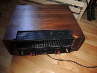
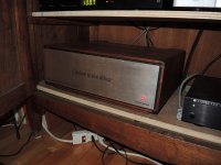
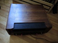
I'll post some pictures I promise when I'll have some free time in the next month... It is a Deluxe oone with the big wood box (repolished as well...). One thing, you'll see with the picture, there seems to be a missing "trim" between front panel and the wood box but all the pictures of a "deluxe" CT12 I've seen seems to be te same...?
Anything else you'ld like to know?
Don't know if it is because the Hitachi lateral FETs but this amp is the best I`ve heard so far home... And I've tried a few...
Problem is I like it so much I put it in my cabinet with the other stuff and cant get it out of there.. I like it too much !!! Warm like tubes and punch and details like a Bryston with a hughe 3D image. Can't ask for better....
I've bought some cct cards from a swedish guy here on DIY and am planning on building another one without any H-K stuff. I have 2 toroidal transfos from a burned SIMA amp, a bunch of PS audio gold 3300 uf 70 V caps ( 3 on each side on each channel ) some new 240 & 9240 FETs with some 1% metal film (I think?) resistors. Can it be better then this one? I'll see. I'm more then really satisfied with this one. Plenty of power, clean and detailed, image and warmth. What more?
I'll post some pictures I promise when I'll have some free time in the next month... It is a Deluxe oone with the big wood box (repolished as well...). One thing, you'll see with the picture, there seems to be a missing "trim" between front panel and the wood box but all the pictures of a "deluxe" CT12 I've seen seems to be te same...?
Anything else you'ld like to know?
Don't know if it is because the Hitachi lateral FETs but this amp is the best I`ve heard so far home... And I've tried a few...
Dooooo Yes I did...
Problem is I like it so much I put it in my cabinet with the other stuff and cant get it out of there.. I like it too much !!! Warm like tubes and punch and details like a Bryston with a hughe 3D image. Can't ask for better....
I've bought some cct cards from a swedish guy here on DIY and am planning on building another one without any H-K stuff. I have 2 toroidal transfos from a burned SIMA amp, a bunch of PS audio gold 3300 uf 70 V caps ( 3 on each side on each channel ) some new 240 & 9240 FETs with some 1% metal film (I think?) resistors. Can it be better then this one? I'll see. I'm more then really satisfied with this one. Plenty of power, clean and detailed, image and warmth. What more?
I'll post some pictures I promise when I'll have some free time in the next month... It is a Deluxe oone with the big wood box (repolished as well...). One thing, you'll see with the picture, there seems to be a missing "trim" between front panel and the wood box but all the pictures of a "deluxe" CT12 I've seen seems to be te same...?
Anything else you'ld like to know?
Don't know if it is because the Hitachi lateral FETs but this amp is the best I`ve heard so far home... And I've tried a few...
Did you get the boards from Tazzz? I've been trying to get a set of boards but if not, I found his schematics. Which output transistors are you going to use in your next build -- more Hitachi? I'm thinking of rebuilding my Citation 12 with IRFP240 / IRFP9240.
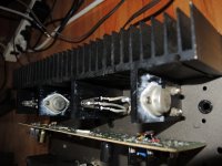
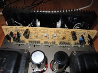
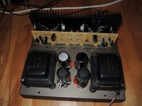
Yes I did bought the set of boards from Tazz. Boards are very well done. If you use a real CT12, you can install IRFP240 & 9240 right on the board and fix all that to the heatsink. For sure this looks nicer then what I did, scratch & jump the existing board, and solder the board connectors to the chassis end. I'll try to take pictures today. I also want to try some speaker cables; good reason to pull it out.
On my next one, I'll use 240 & 9240 FETs. Curious. These FETs worth 1% of the Hitachis but seems to sound quite good. So I'll know.
Actually one thing bothers me a bit with this CT12: When powering off, lt gives a nice "woof" on the speakers. I should install a relay on the output but I'm scared to add anything to this cct that could change the sound a bit... So I disconnect the speakers when turning off. BTW I turn the system off once in a while, every month or so usually. Doesn't heat much. I finally set the bias current to 250ma.
Pictures
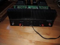
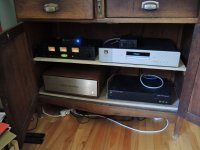
Here they are...
For the next one I'll use a custom chassis. I have 2 toroidal transfos, many filter caps I'll put in parallel (with small value resistor between ), new boards from Tazz I'll populate and I'll use IRFP9240 & 240. Will get back here as well.
QUestion: Tazz suggest me to use a current source with R1, a CRD (current regulation diode); 1N5306 but I can't find this diode anywhere... Newark, Digikey.. I'm just thinking of Mouser. I'll try but anyone knows what I could use instead for limiting current?
Thanks
Attachments
Can somebody post a link to the schematic which was user here?
Also: What are Tazz's boards which were mentioned above?
Here is a link to info on Tazzz's boards. In that thread are images of the boards, his measurements and schematic diagram.
I'm hoping he'll post the gerber files of his boards so we can possibly organize a group buy of some boards.
")
Here they are...
QUestion: Tazz suggest me to use a current source with R1, a CRD (current regulation diode); 1N5306
Thanks
Does the CRD go in parallel with R1? Or, I was thinking of using a separate soft-start solution.
Finally got the diodes!
Happy I won't have to disconnect the speakers terminals anymore when I turn off the amp!
Diode has to be installed in series to limit the current. If it is in parallel, current will be able to go through the resistor & the diode...
I'll get back here when installed to tell the result of this diode installation.
Was pretty $$$ for diodes!
- Home
- Amplifiers
- Pass Labs
- Pass Citation 12