Thanks.If the output impedance of CD Player is less than 1k there shouldn't be any significant difference.
Well, I'd certainly be interested in data - from playing actual music CDs- that other folks measure.
I guess I'd need a newer digital scope? My HP54501 is the newest 'tech' I have and it can get some data like this, but there's no
'Infinite Persistence' setting that I can find.
Well, I didn't find it in the manual
 , but here is 'Infinite persistence' on my HP scope, and also averaging.....
So, I made a test CD with a 1kHz tone at 0dB using the Tone Generator software:
Tone Generator Software ? Sound Frequency & White Noise Generator (PC or Mac)
Loaded up the test CD into my 'shop' Sony CDP and put it on Play-repeat.
Put a 47k resistor across the RCA line output and hooked up my scope(s) and also my UT139 DMM across the resistor.
Results for 0dB CD: 2 v rms out from CDP (5.6 volts p-p) on both HP digital scope (which I wasn't completely sure I was operating properly) and BK analog scope (which I do know how to operate) and the DMM.
So, the CDP is working as specified : 2 v rms output for a 0 dB level CD recording.
Next up: a commercial (not from the home CD burner) music CD : Bonnie Raitt - Luck of the Draw (1991)
Using the HP scope on 'Infinite Persistence' the maximum output level over a few tracks (about 10 minutes of play) was 2.5 v p-p or 0.9 v rms
So, the typical maximum Vrms output from that music CD was about half of the level of the 0 dB test tone, which seems reasonable to prevent clipping on even the loudest transients with a loud recording.
So, now I know that it's not a problem with my CD player in the shop, when I find that an amp isn't playing 'loud enough'...
whatever you do , using FW DIY amp , try to fed it with some decent preamp stage
OP chip based ones aren't ....... either not decent enough , or if decent - certainly not functioning in same spirit
in layman terms - FW amps are all about immediacy and vividness
maybe it's me , but I never made that sort of gain stage with OP chips
OP chip based ones aren't ....... either not decent enough , or if decent - certainly not functioning in same spirit
in layman terms - FW amps are all about immediacy and vividness
maybe it's me , but I never made that sort of gain stage with OP chips
Thanks for doing those tests VictoriaGuy! I been busy and haven't had the time. I'll get back with my results asap. So based on those results, which Diy preamp would be a good project? Any suggestions from the ones on this site where the boards and BOM are available, or others would be appreciated. Something not too complex for a beginner would be great ��.
You mean Op-Amp chip based circuits?whatever you do , using FW DIY amp , try to fed it with some decent preamp stage
OP chip based ones aren't ....... either not decent enough , or if decent - certainly not functioning in same spirit
Do you have any measurements to show that Rod Elliott's #88 isn't decent enough? I'd appreciate seeing them - always willing to learn.
I'm definitely a layman, but not at all allergic to measurements and data.in layman terms - FW amps are all about immediacy and vividness
I'm definitely no good at 'audiophile talk' about PRaT, etc...
Yes, I've noticed that your projects have a few more parts!maybe it's me , but I never made that sort of gain stage with OP chips
Isn't a high parts count contrary to the spirit (simple and elegant) of Mr Pass's designs?
Your amp ( F6 ) is nothing more than an chain link , if you want that chain to be what you like , take a good care of EVERY other links .
F6 can gives you lot more than you ever think , if properly matched ....
;-)
.
That's the next thing I was thinking about - how the F6 would fit into the audio 'chain'.
F6 has a published gain of 14 dB and maximum published output of 25 watts into 8 ohms.
That's about a 5-times voltage gain?
So the very loudest possible output from my CDP -from a 0 dB CD recording - 2 volts rms- would produce 10 volts at the speaker terminals of the F6, with no attenuation or preamp gain between the CDP and the F6 - a 'straight in' connection.. Into an 8 ohm load, that would be 12.5 watts power to the speakers.
The loudest passages from the music CDs I tested (I checked a few more after my previous post) were about 0.9 volts rms at the CDP output jacks.
That works out to 4.5 volts at the F6 output or 2.5 watts.
Typical ('average' not the very loudest passages) music on the CDs I checked was about 0.5 volts rms. That works out to 2.5 volts rms at the F6 output, or 0.8 watts.
So, without some gain from a preamp, the F6 would be performing well below it's maximum potential, playing music from a CDP. At 0.8 watts output, playing 'typical' music from a CD into 85 (?) dB speakers, it shouldn't have surprised me that it didn't seem 'loud enough'
To output 25 watts from the loudest possible (0dB, 2 v rms) signal from the CDP, the input voltage to the F6 needs to be doubled. That's 6dB of gain - as ZenMod and others have (very correctly and accurately
)told me I need in a preamp.And, of course, it's pretty unlikely that the preamp would be operated with the attenuator 'wide open' - unless the speakers were quite inefficient or the room was quite large - , so even the theoretical 'loudest possible CD output' wouldn't get the F6 to the 25W output level.
So the numbers all work out....lots of 'play value' here !
Yes, I've noticed that your projects have a few more parts!
Isn't a high parts count contrary to the spirit (simple and elegant) of Mr Pass's designs?
I think ZM's whole house has less parts than a single op amp. I think op amp circuits can sound fine, but they have a totally opposite design philosophy than the FW stuff.
Maybe the Elliot circuit will get you through, or maybe you will love it forever
Either way, good for you! But you need enough gain before the amp same as you need enough gain before the speaker.Note that the Aleph J has more gain than the F6... though you should still (probably) have a preamp in front of it. I'm sure you will get advice on that if you ask.So based on those results, which Diy preamp would be a good project? Any suggestions from the ones on this site where the boards and BOM are available, or others would be appreciated. Something not too complex for a beginner would be great ��.
You could always build something 'indecent' and upgrade later...
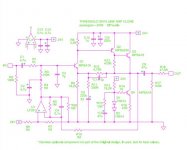
The thing that appealed to me about the Elliott #88 is that the controls are between the gain stages, so the criticisms I got about attenuator impedance and location (at the input to the BOSOZ or at the input to the F6) didn't apply.
And the gain of the #88 can be varied, easily - with jumpers or DIP switches, or by selecting resistor values from a list provided. Since I'm aware that I don't understand SS circuits at all, that was something I liked!
It was also cheap to build. It doesn't use 'unobtanium' jfets (I just today got a (very) little envelope through the mail with $100++ worth of jfets) so it's not a big deal if I blow something up.
And the #88 published specs on noise and distortion are very low. I'm counting on the F6 to add the 2nd harmonic distortion, so a 'straight' preamp was what I was looking for.
And, for the 'parts rollers', some folks find swapping op-amps interesting....which is a simple matter of plugging a different one into the socket - almost as much fun as swapping tubes....
Results for 0dB CD: 2 v rms out from CDP (5.6 volts p-p) on both HP digital scope (which I wasn't completely sure I was operating properly) and BK analog scope (which I do know how to operate) and the DMM.
In case anybody missed it, this means to me that anybody with a quite ordinary DMM (the one I was using was a Uni-T UT139C - $35 USD from China) can make those output measurements from their CDP or other analog source.
The only other thing needed is a 0dB source - a burned CD or output from software of some kind.
It was also cheap to build .......It doesn't use 'unobtanium' jfets .......... 'straight' preamp.
Sounds like you're describing the NS10. I recently built one and although it doesn't have much 'character', It just plain sounds great to me with awesome 'slam'. I've heard people describe the circuit as BRUTAL and honest. A keeper for me.
Don't worry, run the IC pre. If you like it great. If not, make something else.
which reminds me ........ there is official nonsense thread in this forum - http://www.diyaudio.com/forums/pass-labs/135674-pass-pub-high-end-off-topic-thread.html
purpose of that thread is having fun , not group tale chasing

in other words ..... good luck
purpose of that thread is having fun , not group tale chasing
in other words ..... good luck
I don't believe Rod would really take much credit for that pre amp design
I don't understand -
Do you mean that he wouldn't say he designed it?
I know that a lot of that basic info is in the IC app notes, just like most of the famous tube amp circuits came out of the RCA tube manual, etc..
But translating those ideas into something that 'works first time' isn't that easy for a beginner, sometimes. As we can see here, it isn't easy for smart people to 'come down to basic level' sometimes.
Or, that he isn't very proud of that product?
Hey, it works, doesn't oscillate, doesn't hum or add a bunch of noise...so a happy use of a few hours (much less time if I had the PCB on hand).
I think you would need what is called a true rms DMM. The ordinary ones arn't up to it. They're not too bad at mains frequency which is usually what they are designed for but struggle at audio frequencies, don't have any bandwidth
Well, mine worked just fine at 1kHz, which was the frequency for that 0 dB test.
It's always best to test before relying on any instrument, I agree.
which reminds me ........ there is official nonsense thread in this forum - http://www.diyaudio.com/forums/pass-labs/135674-pass-pub-high-end-off-topic-thread.html
purpose of that thread is having fun , not group tale chasing
in other words ..... good luck
Thanks for your contributions to this discussion.
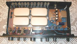
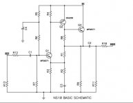
Sounds like you're describing the NS10. I recently built one and although it doesn't have much 'character', It just plain sounds great to me with awesome 'slam'. I've heard people describe the circuit as BRUTAL and honest. A keeper for me.
That's the Pass NS10 discussed in these threads?
http://www.diyaudio.com/forums/pass-labs/61459-ns-10-schematic.html
http://www.diyaudio.com/forums/pass-labs/26003-threshold-ns-10-m1-info-wanted.html
I'm just a beginner at all this, so I don't understand how the schematic and the picture of the NS10 innards quite match up.
What schematic did you use for your build? And which transistors - the ones on the Pass schematic aren't available from 'the usual suspects' like Mouser/Digikey.
Attachments
Well, mine worked just fine at 1kHz, which was the frequency for that 0 dB test.
It's always best to test before relying on any instrument, I agree.
That's good. Take readings at 50Hz and 1kHz just to check
- Status
- This old topic is closed. If you want to reopen this topic, contact a moderator using the "Report Post" button.
- Home
- Amplifiers
- Pass Labs
- Pass Amps- JUst insensitive or is something wrong with my ideas and builds?