those are just (meaning - nothing more and nothing less than) common resistors for upper and lower CCS , distributing auxiliary current , necessary for CCS operation
...
then look for I1 path on Figure 1
thank you again Zen Mod
")
I know what you mean: The current let the transistors of the ccs get open and the ccs work.
But I mean something different. When a signal is attached to the input, there is a voltage drop above the input. Here along the upper CCS.
Its easier if you think of an very simple differential amplifier with collector resistors instead of CCS.
There is an " alternating" voltage drop and current across the collector resistors.
Look again at the Aleph P 1.7
The questions that arise are what happens with that "alternating" voltage drop and current when there is an CCS instead of an Resistor.
Are the bipolor-transistors shifted by that "alternating" current!
I mean the current that the lower ccs gets via the 10k Ohm resistors is only distributed by the bipolar-transistor at the upper ccs.
Is it right?
Sorry if I ask so much
I hope my F4 problem is sorted (see my posts in the F4 thread) but am stil waiting to find out because my friend has not yet had the time to swap the jfets. While I am waiting I decided to go through the stuff I have for my P1.7 and read the related posts on this board.
The P1.7 PCB's were assembled some years ago. I also have the Dantimax volume and input selection kits (these still need assembling) and the cases. When completed I can finally replace my old Yamaha preamp with a great one. Time to tackle this preamp!
I have seen that many people have used many different caps. I recently read Humble Homemade Hifi about the sonic differences between caps and have thought about the caps used in my P1.7 (the 10 uF C9-C16 caps).
The 10 uF caps that are on the boards at the moment are Intertechnik Audyn Cap MKP-QS. I have some spare 10 uF Vishay MKP-1839 in my drawer that I could also use.
I won't ask which is best but wondered what would happen if you combine different brands/types (e.g. C10, C11 MKP-QS + C12 MKP 1839). Do you get "the best of both", "the worst of both" or is it anyone's guess.
Hope you don't mind such a noob question.
Albert
Member
Joined 2009
Paid Member
Hi Scott,
I am working on the layout of the front panel of the Alpeh P1.7 I am building and came across the photo's you posted of your P1.7 in post #124. Your amp looks terrific!
I am trying to figure out how to get the display (OLED 2x16 Newhaven) to fit nicely, what type of knobs and switches to use, etc.
It looks like you used the same Hifi2000 Slimline 2U 10mm enclosure and Dantimax kits I bought and it would be mighty helpful to see how you solved it.
Would you mind posting some more details and pictures of the front panel (and if possible the also of the reserve side)? You can also PM me if you prefer.
Thanks,
Albert
albertNL:
I don't have any photographs that would help explain the milling of the space for the LCD display, but I would be happy to send you (and anyone else who may be interested) the final Front Panel Design file for my Aleph P 1.7.
Even if you don't use Front Panel Express, you could download their software to view my design, which might help in your project.
I'll send you a PM.
Regards,
Scott
albertNL:
I don't have any photographs that would help explain the milling of the space for the LCD display, but I would be happy to send you (and anyone else who may be interested) the final Front Panel Design file for my Aleph P 1.7.
Even if you don't use Front Panel Express, you could download their software to view my design, which might help in your project.
I'll send you a PM.
Regards,
Scott
Thanks Scott. I just sent you a PM with my email address.
It might be a good idea to start a new thread where people can upload fpd files and photo's of completed projects. I will do so and upload my Aleph-J photo and FPD file.
Albert
possible - yes
wise - no
Many thanks for your reply it's really mean for newbie like me
, actually that's my second unit for 1.7 and i need to try something different - i will make it cheap as possible ,As you see that unit it has been made by really cheap part - hand made PCB , mila cap , bi cap by used wima , metal film resistor . All of those should not exceed 40 USD (stereo)1) i have not enough heatsink then i just ask is it possible to remove it ,and yes it should not( thanks Zen Mod)
2) can i use 24-0-24 transformer to feed 48 vac to power supply . Is that enough to operate p1.7?( because in my country 24-0-24 is general and cheaper than 60-0 or 30-0-30 and i already have a pair of it)
3) for the pot 2k for gain control - shall we replace it by a fix resistor - if it can what is the suitable rating ?
I have some question to bother you guys here
If it possible for you all to help me to clarify those issue , i will have really appreciated.
Last edited:
referencing to sch in Service Manual
1. simple - if any of mosfets is too hot to touch it , put piece of Al tin on ; you can find suitable donor heatsink in any dead computer PSU
max. dissipation per any mosfet in 1.7 is bellow 1W ; usually not problem for them even without heatsink
2. just ignore center tap on secondary and that's 48Vac
3. ordinary small resistor will do
new board on the block
FYI only:
http://www.diyaudio.com/forums/group-buys/262974-aleph-p-back-limited-time-offer.html#post4080221
I am finally moving (well slowly), on my AlephP project. it has been on the backburner for a while. if there are others interested, please let me know (use that post in group buys though. Thanks.).
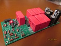
started stuffing the board (all transistors still missing but just to give you an idea). I also left one Wima cap out so you can see the other relay tucked in between (yours will be the shorter 4-pin version; I bought 5-pin ones as surplus stock, remember?).
I also realized the rectifier pins (i.e. orientation) are not labeled on the board (sorry). the one that connects to the large 2200uF cap is "+" and the the one on the other end next to the AC_in block is the grounded "-". the two in the middle are AC. if you use the same rectifier as me (Fairchild GBU4) the text will be facing in towards the board. I am still working on a little hsink for the rectifier (probably an overkill) so it is not mounted yet and thus there is no pic available at this time.
I also realized the rectifier pins (i.e. orientation) are not labeled on the board (sorry). the one that connects to the large 2200uF cap is "+" and the the one on the other end next to the AC_in block is the grounded "-". the two in the middle are AC. if you use the same rectifier as me (Fairchild GBU4) the text will be facing in towards the board. I am still working on a little hsink for the rectifier (probably an overkill) so it is not mounted yet and thus there is no pic available at this time.
Attachments
My boards just arrived. Beautiful job Koja! Two questions though... Is there a parts list for this project yet? I doubt any of us are going to need a complete general parts list but I would love to know the part numbers for the relays and the DIP switch. The rest of it is easy.
Best to all!
Mark
Best to all!
Mark
No official BOM, only pointers are available.
relays:
2X Hamlin HE722A0510 (these control the input attenuator switches)
any 4-pole DIP switch will do the job.
2X Coto Technology 9007-05-01 with the protection diode included (or 9007-05-00 without the built in diode which can be added under the board, instead of on the pcb where it may be too far). these relays are to ground the negative input and output respectively if either is used unbalanced.
again: you need an external 5V PS to drive the relays! (I will use the PS which at the same time drives 1kOhm RelVol Attenuator by dantimax.dk).
4-pin rectifier bridge (Fairchild GBU4G)
electrolitic caps in PS:
the first one: 2,200uF/100V cap instead (snap in P:10mm 25x50mm(DxH); (mine is Panasonic ECO-S2AA222CA); the rest are all P:10mm. 20x36(DxH) (I have Nichicons 1000uF/100V UVR2A102MRD6).
the resistors are assumed to fit the footprint: P:10.35mm; body:6.8(L) x 2.8mm(Diam)
only R44 and R59 (22.1Ohm) off the rail are stood up vertically, and R73 (3.3Ohm/2W) is on a bigger footprint P:20; body: 16.5(L) x 6.5(diam).
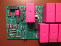
p.s. you can see in my pic that I have a lot of slightly oversized Dale RN60D resistors and I had to bend their leads under a bit but they could still fit, only the board does not look its best.
-----------------
and again: for this board you will need a pencil soldering tip and make sure the solder flows through the hole and shows up on the top side, since the pads are really small (for maximizing the ground plane poured all around). I am not happy with the pads for the electrolitic caps; I used the standard footprint from Altium library and did not check them so it tourned out that my caps have thick leads and the holes and pads are both undersized. Sorry.
relays:
2X Hamlin HE722A0510 (these control the input attenuator switches)
any 4-pole DIP switch will do the job.
2X Coto Technology 9007-05-01 with the protection diode included (or 9007-05-00 without the built in diode which can be added under the board, instead of on the pcb where it may be too far). these relays are to ground the negative input and output respectively if either is used unbalanced.
again: you need an external 5V PS to drive the relays! (I will use the PS which at the same time drives 1kOhm RelVol Attenuator by dantimax.dk).
4-pin rectifier bridge (Fairchild GBU4G)
electrolitic caps in PS:
the first one: 2,200uF/100V cap instead (snap in P:10mm 25x50mm(DxH); (mine is Panasonic ECO-S2AA222CA); the rest are all P:10mm. 20x36(DxH) (I have Nichicons 1000uF/100V UVR2A102MRD6).
the resistors are assumed to fit the footprint: P:10.35mm; body:6.8(L) x 2.8mm(Diam)
only R44 and R59 (22.1Ohm) off the rail are stood up vertically, and R73 (3.3Ohm/2W) is on a bigger footprint P:20; body: 16.5(L) x 6.5(diam).
p.s. you can see in my pic that I have a lot of slightly oversized Dale RN60D resistors and I had to bend their leads under a bit but they could still fit, only the board does not look its best.
-----------------
and again: for this board you will need a pencil soldering tip and make sure the solder flows through the hole and shows up on the top side, since the pads are really small (for maximizing the ground plane poured all around). I am not happy with the pads for the electrolitic caps; I used the standard footprint from Altium library and did not check them so it tourned out that my caps have thick leads and the holes and pads are both undersized. Sorry.
Last edited:
- Home
- Amplifiers
- Pass Labs
- Pass Aleph P 1.7 preamp builders thread