Gainblock....
I have designed this gainblock.. Gain is set at app 40dB...low distortion almost nothing and only 2. order..
Don't know how to calculate noise, but I do believe it's quite Lowish....
5 mA through the fet's and similar impedance on both sides of the LTP
Total Harmonic Distortion: 0.000704% or so LT-spice says...
Attachments
Last edited:
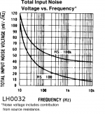
PS, just discovered that I can get easily get the LH0032, does anyone know if the noise is low enough for MM Phono?
From nat-semi datasheet, in case some are still looking
Attachments
Gainblock....
I have designed this gainblock.. Gain is set at app 40dB...low distortion almost nothing and only 2. order..
Don't know how to calculate noise, but I do believe it's quite Lowish....
5 mA through the fet's and similar impedance on both sides of the LTP
Total Harmonic Distortion: 0.000704% or so LT-spice says...
Hi MiiB,
This is a good start, and in many ways is along the lines of what I have been doing. However, I would have expected the load on J1 (through the cascode) to have been a current mirror. Maybe I am missing something. Also, be cautious about the use of a tail resistor instead of a current source, as common mode rejection becomes important, including for noise performance. However, also be aware that current sources make noise, especially when they have a fairly low value of emitter degeneration resistance. Consider using a cascoded current source with a high value of emitter resistance and a very low noise reference voltage. Keep in mind that good common mode rejection out to fairly high frequencies is very helpful.
Watch out for all of the noise contributors, including the emitter resistors combined with the folded cascodes. You want to be sure that all noise contributors are small compared to the noise contributed by the input JFETs. Also, think carefully about how you bootstrap the cascode bases and the effect it will have on the performance of the input stage.
For noise analysis, I suggest you use an LTspice noise analysis. How to do this is shown and discussed in Chapter 19 of my book "Designing Audio Power Amplifiers".
You may also find some of the transistor models on my web site useful (including the LSK389), but always remember that SPICE models for the noise performance of JFET and bipolar transistors are often not as close to reality as we would like. Some of the manufacturers' SPICE models for BJTs are not even remotely close. In my upcoming posting on the site of revised transistor models I have sought to provide much better values for RB so that noise conformance to real-world noise measurements that I did is better. Getting those revised models up on the web site is now in the hands of my web designer (my son). Many of the current BJT models on my site still have manufacturers numbers for RB even though I refined many of the DC and AC parameters to better fit measurements and or spec sheet information.
Cheers,
Bob
Gainblock....
I have designed this gainblock.. Gain is set at app 40dB...low distortion almost nothing and only 2. order..
Don't know how to calculate noise, but I do believe it's quite Lowish....
5 mA through the fet's and similar impedance on both sides of the LTP
Total Harmonic Distortion: 0.000704% or so LT-spice says...
I Like this one! Personally I would lose the output stage and feedback and insert a transimpedance riaa. I would also use a full current mirror (with noise optimized emitter resistors) and a ccs in the tail. I think we are getting somewhere
")
Something like this. Disregard the component values!
View attachment fetriaa.pdf
//Anders
Last edited:
Hi Tvi,
Many thanks. Looks a trifle noisy, but no worse than a good ECC83 and it is possible to build quite decent phono stages (noisewise at least) using these...
So, a much easier Kanata using LH0032 may worth a try...OLG vs. frequency and other stuff looks goo, plus we can tap in before the output stage.
Getting WAY off topic though, back to the thread.
Ciao T
From nat-semi datasheet, in case some are still looking
Many thanks. Looks a trifle noisy, but no worse than a good ECC83 and it is possible to build quite decent phono stages (noisewise at least) using these...
So, a much easier Kanata using LH0032 may worth a try...OLG vs. frequency and other stuff looks goo, plus we can tap in before the output stage.
Getting WAY off topic though, back to the thread.
Ciao T
Output stage
After the transimpedance riia i would connect to an output stage looking something like this....
View attachment Tubeout_1.pdf
Or this one if one likes to keep it simple and absolute phase is not an issue.
In this one i would trim the dc output from the input stage to properly bias the tube stage and avoid passives on the cathode of the first tube.
View attachment Tubeout_2.pdf
Again, disregard component choises and values!
It is my experience that this cathode follower is VERY transparent!
//Anders
John,
Of course they are nothing new. They seem to make a renaissance in circles I find interesting. It seems the followers of Kaneta "discovered" this chip and the fact that it looks on the inside a lot like a lot of Kaneta's designs...
So wanting to play with this chip has it's own reasons.
I like the OLG vs. Frequency a lot, not much gain (barely enough for a MM RIAA), but as fast as greased lightning and simple.
For MC we can always use the "single stone headamp" using up one of my small collection of 2SK146 or snipping some 2SK369 from the reel... ;-) Using one on of my few samples of INF146 may be cool, because then all active components will be Mil-Spec in metal cases.
I can mate that with my Mil-Spec east german polystyrene cap's, what a blast from the past. In the right circles bragging rights should be high.
Anyway, off topic for this thread, appypollylogies...
Ciao T
Guys, the LH0032 is a waste of time. We can make better designs, certainly quieter ones. It was NOT designed for audio, but for military application. Dick Marsh tried these units out 30+ years ago. They are nothing new.
Of course they are nothing new. They seem to make a renaissance in circles I find interesting. It seems the followers of Kaneta "discovered" this chip and the fact that it looks on the inside a lot like a lot of Kaneta's designs...
So wanting to play with this chip has it's own reasons.
I like the OLG vs. Frequency a lot, not much gain (barely enough for a MM RIAA), but as fast as greased lightning and simple.
For MC we can always use the "single stone headamp" using up one of my small collection of 2SK146 or snipping some 2SK369 from the reel... ;-) Using one on of my few samples of INF146 may be cool, because then all active components will be Mil-Spec in metal cases.
I can mate that with my Mil-Spec east german polystyrene cap's, what a blast from the past. In the right circles bragging rights should be high.
Anyway, off topic for this thread, appypollylogies...
Ciao T
Hi,
This looks a lot like the latest SS Phono from Phase Tech, except they do all of it strictly single-ended, so 1pcs 2SK170 IIRC, PNP current mirror with CCS load to negative rail (servo to CCS), transimpedance RIAA, Fet Buffer and done. The source of the K170 returns via a resistor to negative rail, so it possible to adjust gain freely and switch between MC and MM, which they do.
With a K170BL at Idss you get around 35mA/V, so for 80dB gain at DC you need around 300K load, almost suits a RIAA with 10n/3.3n Caps...
I do like that RIAA's Zen Style... Could be a bit of a hassle to get to work though. And noise is higher than 10R of course.
Ciao T
Something like this. Disregard the component values!
View attachment 221560
This looks a lot like the latest SS Phono from Phase Tech, except they do all of it strictly single-ended, so 1pcs 2SK170 IIRC, PNP current mirror with CCS load to negative rail (servo to CCS), transimpedance RIAA, Fet Buffer and done. The source of the K170 returns via a resistor to negative rail, so it possible to adjust gain freely and switch between MC and MM, which they do.
With a K170BL at Idss you get around 35mA/V, so for 80dB gain at DC you need around 300K load, almost suits a RIAA with 10n/3.3n Caps...
I do like that RIAA's Zen Style... Could be a bit of a hassle to get to work though. And noise is higher than 10R of course.
Ciao T
After the transimpedance riia i would connect to an output stage looking something like this....
View attachment 221561
Or this one if one likes to keep it simple and absolute phase is not an issue.
In this one i would trim the dc output from the input stage to properly bias the tube stage and avoid passives on the cathode of the first tube.
View attachment 221562
Again, disregard component choises and values!
It is my experience that this cathode follower is VERY transparent!
//Anders
Anders how do you define the the DC bias point of the first anode into the 2nd grid?
jan didden
John,
Of course they are nothing new. They seem to make a renaissance in circles I find interesting. It seems the followers of Kaneta "discovered" this chip and the fact that it looks on the inside a lot like a lot of Kaneta's designs...
So wanting to play with this chip has it's own reasons.
Ciao T
Not chip, hybrid. You could do better with your own SMT "clone" with modern transistors.
Ears only!
1) Noise is over rated!
2) Did you listen to these hybrids?
3) Why must it be new?
4) It blows away all chips specially designed for audio like OP275, OPA604 and all the recent AD and TI crap.....(in my DAC)
5) Sorry John blowing your bubble.

Ears only!
Guys, the LH0032 is a waste of time. We can make better designs, certainly quieter ones. It was NOT designed for audio, but for military application. Dick Marsh tried these units out 30+ years ago. They are nothing new.
1) Noise is over rated!
2) Did you listen to these hybrids?
3) Why must it be new?
4) It blows away all chips specially designed for audio like OP275, OPA604 and all the recent AD and TI crap.....(in my DAC)
5) Sorry John blowing your bubble.
Ears only!
Attachments

Last edited:
Anders how do you define the the DC bias point of the first anode into the 2nd grid?
jan didden
By controlling the dc offset in the output of the input stage.
//A
Front end ... modified to be non feedback transconductance
Would like to have the high frequency (75 us) filter passively in front of the second gain block where I'll the insert the base shelf (318-3180us) actively in the feedback loop..
Now trouble begins..or my limited knowledge come into play.... How on earth to get a precise riaa curve out of this...??
As the Amplification drops with the reduced impedance..The two things are pulling the same direction.. and..difficulty is with the 75 us pole....so so difficult to get right on the money
Calculations anyone..??
Performance still good.. lowish distortion and nice distribution...no harmonics higher an 3.th order and that is already below -80 dB
Would like to have the high frequency (75 us) filter passively in front of the second gain block where I'll the insert the base shelf (318-3180us) actively in the feedback loop..
Now trouble begins..or my limited knowledge come into play....
How on earth to get a precise riaa curve out of this...??As the Amplification drops with the reduced impedance..The two things are pulling the same direction.. and..difficulty is with the 75 us pole....so so difficult to get right on the money
Calculations anyone..??
Performance still good.. lowish distortion and nice distribution...no harmonics higher an 3.th order and that is already below -80 dB
Attachments
Hi,
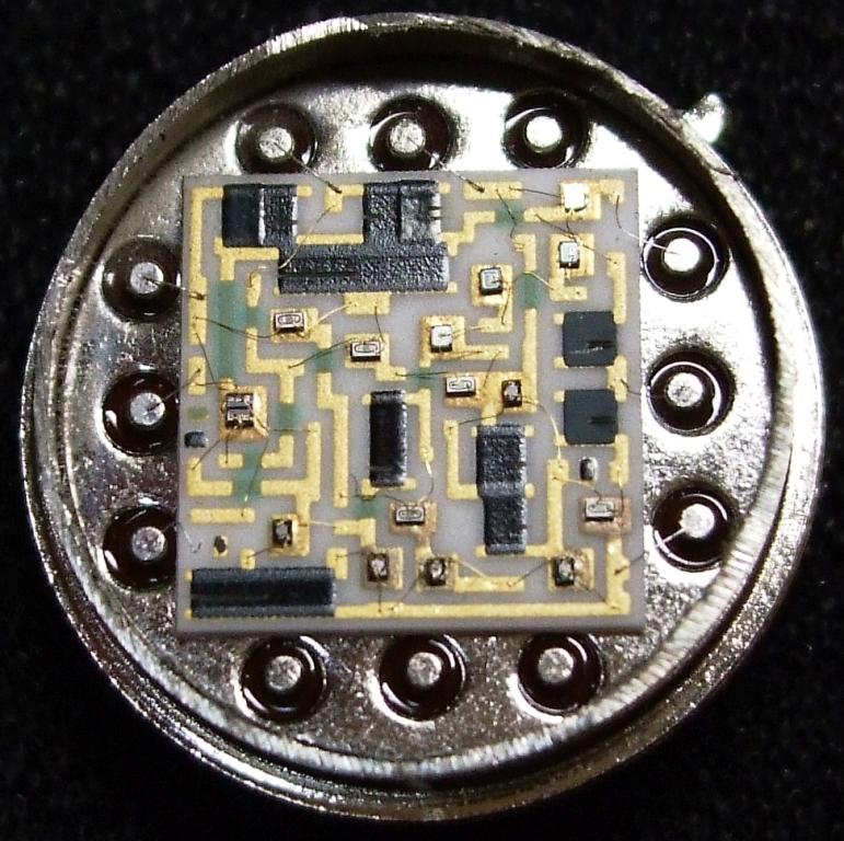
I (kinda) forgot how they made these thickfilm hybrids. That is already beyond SMD, I love it.
I'm not surprised it beats up all the monolithic stuff.
This is basically a nice, latter day Kaneta Pre done is "smaller than SMD". Now I know there are detractors, but the Kaneta stuff I got to hear was pretty good.
Are the later Nat Semi ones Thickfilm or later monolithic ones? I suppose the picture you show is Calogic?
Ciao T
4) It blows away all chips specially designed for audio like OP275, OPA604 and all the recent AD and TI crap.....(in my DAC)
http://www.diyaudio.com/forums/attachments/analogue-source/221596d1304539145-parasound-jc3-phono-lh0032.jpg.jpg
I (kinda) forgot how they made these thickfilm hybrids. That is already beyond SMD, I love it.
I'm not surprised it beats up all the monolithic stuff.
This is basically a nice, latter day Kaneta Pre done is "smaller than SMD". Now I know there are detractors, but the Kaneta stuff I got to hear was pretty good.
Are the later Nat Semi ones Thickfilm or later monolithic ones? I suppose the picture you show is Calogic?
Ciao T
It's a NS
Picture came from here:
(  ̄? ̄)*???: ?????!LH0032
See also:
http://www.diyaudio.com/forums/anal...rch-preamplifier-part-ii-682.html#post2373150
Picture came from here:
(  ̄? ̄)*???: ?????!LH0032
See also:
http://www.diyaudio.com/forums/anal...rch-preamplifier-part-ii-682.html#post2373150
- Status
- This old topic is closed. If you want to reopen this topic, contact a moderator using the "Report Post" button.
- Home
- Source & Line
- Analogue Source
- Parasound JC3 Phono