Not universal at all.......
Hi,
I have browsed this thread with great interest since i´m looking for inspiration for a phono stage that is a bit more universal than the one i am using now. The input stage of my current (pun intended) riaa you can see below, sans servo. I have used it for quite some time and it works (sounds) VERY good on the low impedance carts i use, SPU and Audio Note I/O. On carts with a little higher generator impedance it does sound a bit "over damped" if you will. I also use the same topology for I-V conversion in my dac but with 2sc2240/2sa970.
The output stage in the riaa is..........a tube stage......
BTW, i am not to happy about the idea of an integrated opamp as the second stage here, open loop allways sound better to my ears if done right.
BR,Anders
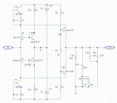
Attachments
Bappe, this is a good design, with limited application. At this time, fixed, VS variable cartridge loading is being discussed by my associates. We did NOT put variable loading in the JC-3 design. Was this a mistake? To me, being sort of lazy about this cartridge loading thing, I usually am happy with a choice of 100 ohms and 47K ohms for the typical optimal loading, but a number of my associates are NOT! Just as they have an obsession with absolute polarity, they also work hard at optimum cartridge loading. I have heard both effects, and VTA as well. However, when I want to just listen to a favorite record, I don't want to go through the bother. However, my associate, Brian Cheney, who maintains a listening room to show clients the quality of his speakers, is seriously concerned with each and every variable, and every record is marked for polarity, and he gets his cartridge loading to about 1 ohm resolution. It just depends.
Now, back to summing inputs. They work, but not universally, so they are discouraged in this discussion.
Now, back to summing inputs. They work, but not universally, so they are discouraged in this discussion.
Last edited:
Scott,
I just came across actual micro-diodes. 1N4148_Q Fairchild Semiconductor Rectifiers
At a truly reasonable price!")
End of life clearance!
ES
I just came across actual micro-diodes. 1N4148_Q Fairchild Semiconductor Rectifiers
At a truly reasonable price!
End of life clearance!
ES
Scott,
I just came across actual micro-diodes. 1N4148_Q Fairchild Semiconductor Rectifiers
At a truly reasonable price!
End of life clearance!
ES
Digi-Key is stocking our new 1nV in-amp AD8229 @ $163.15. Can you guess why? (nothing to do with the military) Hopefully I'll get to repeat my stacked amplifiers lower noise article from EDN.
Can you guess why? (nothing to do with the military)
Just to screw with our heads?
Just to screw with our heads?
You especially will appriciate this, 210C operation for down hole instruments. Lead customers are in Texas, no surprise. There will be a normal version eventually.
You especially will appriciate this, 210C operation for down hole instruments. Lead customers are in Texas, no surprise. There will be a normal version eventually.
Well let's see, that is above the melting point of virtually all tin lead solder alloys! So how do you build the rest of the circuit?
So how do you build the rest of the circuit?
Welded connections or high temp solder, totally different mindset on just about everything, and don't forget $$$. BTW these are by and large one use instruments.
MC cartridge loading thoughts
When considering MC cartridge loading, I think we need to take into account the cartridge inductance and its effect on frequency response. This is especially true if the cartridge is feeding a virtual ground (summing node) input. This is why I was asking about MC cartridge inductance awhile back. Its unfortunate that MC cartridge manufacturers don’t ever seem to publish inductance values.
The time constant/pole frequency formed by the cartridge resistance and inductance is of particular interest. Consider a cartridge with resistance of 10 ohms and inductance of 100 uH. The corner frequency for this is 15.9 kHz. This means that if this cartridge drove a perfect virtual ground it would be down 3 dB at 15.9 kHz without considering any other factors. This effect alone can account for much of the perceived decrease in sound quality when an MC cartridge is loaded with a virtual ground.
Now consider a 50 uH cartridge loaded with the usual 100 ohms. The pole frequency thus formed will be at 318 kHz, well above audibility. MC cartridges with higher output, perhaps in the 500 uV range, can be assumed to have higher inductance than those whose output is only 50 uV. Similarly, it is likely that an MC cartridge with 50 ohms DCR will have higher inductance than one with 5 ohms DCR. Even a cartridge with 200 uH inductance loaded by 100 ohms will exhibit a pole at 80 kHz, also adequately above audibility (this might cause a loss of a few tenths dB at 20 kHz). However, it is clear that such a cartridge loaded with a significantly smaller resistance will begin to lose some high end response.
There appear to be at least 4 possible consequences of low-Z loading on an MC cartridge.
1. HF frequency response roll-off as discussed above.
2. Possibly reduced ringing in the transient response due to electrical damping; this is largely another frequency response effect.
3. Increased electrical damping might affect the mechanical movement of the needle in such as way as to reduce distortion at high groove velocity. The possible degree of this effect seems to be very unclear and might be difficult to measure.
4. The increased current flowing in the coil might excite some nonlinearity. This appears to be the effect that Risch was trying to counteract with the use of a replica cartridge in the feedback path. A cartridge with 5 ohms DCR and producing a peak output of 2mV (20 dB above nominal of 200 uV at 5cm/sec) will experience peak currents of only 0.4 mA when driving a virtual ground. It seems difficult to believe that this will create any nonlinearity due to core nonlinearity. This effect should be measurable with an appropriate THD analyzer setup where the cartridge is driven with a small AC signal current of less than 1 mA at frequencies low enough not to excite any mechanical resonances.
Cheers,
Bob
I firmly state that 10uH is the TYPICAL inductance for a quality MC cartridge. There may be exceptions, but they are not of much interest here. All anyone needs to do, is a little research.
What does L have to do with anything Bob said?
Its unfortunate that MC cartridge manufacturers don’t ever seem to publish inductance values.
Maybe it is very difficult (or costly) to measure cart inductances . Maybe the OEM are afraid others might copy their setup if they disclosed such an important parameter.
I guess it would be very simple to calculate a good aproximation for opt cart load using maths if we knew all the relevant values.
This guy even placed a link with a calculator for that effect:
Hagerman Technology LLC: Cartridge Loading
Now he states a "good" MC cart impedance to be at 5~0.5mH so there seems to be a large gap difference of points of view here.
Another guy stated the following very interesting point of view: MC cartridge loading [Archive] - The Art of Sound Forum
MC cartridge loading - The Art of Sound Forum
"Koetsu recommend a loading of 50 to 1000Ω for the Black. 470Ω would seem to be just right. The coil resistance is 5Ω, so the load impedance is 94x the coil resistance. Any value greater than 10x is usually OK. I don't know what the coil inductance is, but it will be something like 5mH. If the coil resistance is sufficiently small that it can be ignored relative to the load impedance, then the series combination of coil inductance and load resistance will have a -3dB point at R/(2πL) or in this case 470/(2π 5.10 ̄-³) = 15kHz. This is one reason to choose a higher resistive loading."
Now this is food for the minds
Why so many different points of view ? It looks we are near a very sensible subject.
Regards
Ricardo
Ricardo, thanks for the Hegerman link that you put up. It is NOT impossible to find the inductance, but your GUESS is off by about 500 It is only 10uH or so. Please be more careful. That is what I am trying to point out to Bob Cordell. IF you want to know the truth, do some searching on the internet. I will not be easy, but it is possible.
Goldring Eroica H 200uH (HO)
Goldring Eroica L 3uH (LO)
Goldring Eroica LX 12uH (LO)
Denon DL-304 50uH (0.18mV)
Denon DL-103 56uH (0.3mV)
Denon DL-103SA 380uH (0.25mV) Wonder if inductance is correct?
Denon DL-160 490uH
AT-OC9 50uH
Some of this information came from the Art of Sound Forum MC cartridge loading [Archive] - The Art of Sound Forum
the rest I just kind of found here and there. I can't vouch for the absolute reliability of these numbers.
I believe some of the Ortofon SPU reissues are well under 10uH FWIW. (Did not have the opportunity to measure the one I broke years ago, and the next one will be treated with great care)
Last edited:
I found some numbers, also: Lyra Kleos 5.4 ohms, 9uH, Delos 8.5 ohms 9.5uH
To make sense of ANY inductance, you MUST also post the DC resistance, because that will create the pole with the inductance in a summing input.
As can be noted, high output MC cartridges will have extra high inductance. This is normal, but NOT a good criterion for understanding summing type input differences.
- Status
- This old topic is closed. If you want to reopen this topic, contact a moderator using the "Report Post" button.
- Home
- Source & Line
- Analogue Source
- Parasound JC3 Phono