PatPet said:That means I benefit from something like OS without losing the pros of non-OS with staggering DAC
Afraid not. As with many other things the conditions have to be right in order to get the best performance and in this case the relevant condition is the number of samples. The process makes a basic assumption about the waveform and for that assumption to be valid there has to be a reasonable amount of samples particularly in the higher frequencies. Therefore if you do not precede the process with an OS filter it will still work but expect to loose your higher frequencies.
rfbrw said:
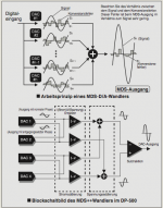
From MJ 3/1993. The digital filter feeding the registers is the SAA7220P/B. Dacs are 4 PCM56 per channel. The registers are 74HC164.
I'm new to shift register. But I don't understand how the data lines are delayed by half a sample from each other. What I know is the adjacent outputs have a CLK period delay. Could anyone explain more to me?
If I'm going to implement 4X or 6X OS, what is the equivalent block diagram?

PatPet said:
If I'm going to implement 4X or 6X OS, what is the equivalent block diagram?
I think the schematic for a x4 os was posted here.
The question is if it is worse the trouble.
You will have linear interpolation which will worsen linearity because you get additional samples that are not located on the desired waveform.
Distortion will rise with frequency because of less samples.
Logic chips could bring additional jitter.
Bernhard said:
I think the schematic for a x4 os was posted here.
The question is if it is worse the trouble.
You will have linear interpolation which will worsen linearity because you get additional samples that are not located on the desired waveform.
Distortion will rise with frequency because of less samples.
Logic chips could bring additional jitter.
The above is only true if you do not know what you are doing.
PatPet said:
I'm new to shift register. But I don't understand how the data lines are delayed by half a sample from each other. What I know is the adjacent outputs have a CLK period delay. Could anyone explain more to me?
An explanation of shift registers.
http://www.eelab.usyd.edu.au/digital_tutorial/part2/register02.html
If I'm going to implement 4X or 6X OS, what is the equivalent block diagram?
Post #71. 4x for data in the same format as the output of the SAA7220.
rfbrw said:
The above is only true if you do not know what you are doing.
I don't know what I do.
rfbrw said:
An explanation of shift registers.
http://www.eelab.usyd.edu.au/digital_tutorial/part2/register02.html
Post #71. 4x for data in the same format as the output of the SAA7220.
Adjacent output is delayed by how many samples?
How do you calculate that?
For post 71
Why are the 6 74HC164s cascaded? What do R1-4 L1-4 and LE1-4 represent?
Dear,
Looking at accuphase closer. They not "just" stack or parallel dac chips. In a part they parallel (two from the four available dac's)the current outputs. The other halve they summ the voltage signal after the I-V converters. So they not stack all the DAC's directly
http://www.accuphase.com/model/pdf/dp-78_e.pdf
I remember Kenwood (in a parallel dac design) gives each of the 6 dac chips it's own I-V converter. And summ the voltage signal after the I-V converters. Each I-V converter have it's own feebackloop. Each indicidual I-V converter opamp will try to correct the error seen from the other I-V converter stagea. Errors caused by either the dac chip or the I-V converter. This wil reduce THD. Accuphase try to do both in one design. For a part benefit from the higher signal caused bij paralleling the current outputs from the Dac chips. And the same time let the I-V convertor opamps bij paralleling correct errors.
For example if I-V opamp 1 spit out an error. I-V opamp 2 and 3 will try to correct this and send a correction signal in opposite phase. and so on and so on... Clever!
Best regards,
Bas
So, resurrecting this thread, BB/TI simply soldered together the current outputs of 4 PCM1704 DACS to feed one I/V stage?
http://focus.ti.com/lit/ug/sbau029/sbau029.pdf
They missed to draw a junction between the current outputs of the second and first pair PCM1702 in the schematics, (Page9 and Page10, close to the Iout symbol) did they miss something else in paralleling those dacs?
Would like to do this with 8 PCM1704 as well...
All the best,
Salar
Last edited:
digital crossover would seem to be another method of usefully combining multiple DACs per channel
each DAC sees only a limited portion of the audio frequencies, reducing IMD
for parallel DACs with processing power you could also use "subtractive dither" - dither patterns in each DAC's drive that adds to zero in the summed output
each DAC sees only a limited portion of the audio frequencies, reducing IMD
for parallel DACs with processing power you could also use "subtractive dither" - dither patterns in each DAC's drive that adds to zero in the summed output
With the slight offset technique, 8x plain pcm1704 , might be easily better than 8x pcm1704K in ordinary parallel.
I dont see the need for dither with 24bit wordlength , it'd be useful to feed 16bit chips ( which are up to 20bit accurate) 24bit data, but 1704 should do without it , has no glitch anyway -with constant HF dither, the input is never 0 , obviously.
I dont see the need for dither with 24bit wordlength , it'd be useful to feed 16bit chips ( which are up to 20bit accurate) 24bit data, but 1704 should do without it , has no glitch anyway -with constant HF dither, the input is never 0 , obviously.
Last edited:
Attachments
 I recently buy an used HK HD760 which uses one PMD100 and 4xPCM1702.
Logic between PMD100 and DAC uses a "may be so called" parallel shifted DAC configuration (see link below)
http://www.neufgiga.com/n/50-17/share/LNK29974de57549c7d68/
Is it really some kind of linear interpolation depicted in post 42 in this thread ?
Is it worth the case as opposed for instance making balanced dac with a 74HC86 ?
N.B : pmd100 is configured as 16 bit right justified and output 20 bits in 2's complement mode. DOL and DOR seems to be delay for 12 BCK cycle (I'm not sure)
Thx, what could the benefit of "averaging" this way ?
simple analog LPF which is the case and ...?
It could have been simplier to let the PMD100 oversample (8x in soft mode, mode they choose) and paralleling the DAC chips without delaying DATA (as depicted in PCM1702 evaluation board). But I guess there won't be many people who compared the two configuration.
- Status
- This old topic is closed. If you want to reopen this topic, contact a moderator using the "Report Post" button.
- Home
- Source & Line
- Digital Source
- Paralleling up DAC chips