No and no. Assuming you don't use just one 40000uF cap, but multiple in parralel, the total ESR will already be very low, possibly even lower than the poly cap on it's own. And the added 10uF is peanuts in terms of capacitance compared to the already avaliable amount.
There are situations where parralelling e.g. a film cap is benificial. If the bank has an impedance peak for example, you can reduce this, but not knowing if, and at what frequency this peak exists, you could also make things worse. That's whay 'just adding' a random cap of random value is a bad idea.
There are situations where parralelling e.g. a film cap is benificial. If the bank has an impedance peak for example, you can reduce this, but not knowing if, and at what frequency this peak exists, you could also make things worse. That's whay 'just adding' a random cap of random value is a bad idea.
Last edited:
Actually, it can possibly have benefits.
The ESR of those large caps is at relatively low frequencies. At high frequencies the caps don't "look" so good. So the paralleling of a film cap that continues to operate at higher frequencies can help to shunt HF stuff, including pulses from the rectifier and from the line itself (assuming any pass through or bypass the transformer and the main caps.
So, sure no harm, no foul by putting the film cap across the electrolytic cap.
_-_-bear
usually the big caps are nowhere near the actual load "demand" point of the active output device collector/drains
the physical distance involves trace and wiring - which adds so much extra L and R to the point that you simply can't see the effect of the tiny cap placed across the big caps
put local RF bypassing with required/designed high frequency well damped low Z performance at the output device leads - not at the big caps end of the ps wires/trace
rectifier snubbers should be across the diodes or the xfmr secondary pair entry into the bridge
Last edited:
usually the big caps are nowhere near the actual load "demand" point of the active output device collector/drains
the physical distance involves trace and wiring - which adds so much extra L and R to the point that you simply can't see the effect of the tiny cap placed across the big caps
put local RF bypassing with required/designed high frequency well damped low Z performance at the output device leads - not at the big caps end of the ps wires/trace
rectifier snubbers should be across the diodes or the xfmr secondary pair entry into the bridge
Strongly concur.
usually the big caps are nowhere near the actual load "demand" point of the active output device collector/drains
the physical distance involves trace and wiring - which adds so much extra L and R to the point that you simply can't see the effect of the tiny cap placed across the big caps
put local RF bypassing with required/designed high frequency well damped low Z performance at the output device leads - not at the big caps end of the ps wires/trace
rectifier snubbers should be across the diodes or the xfmr secondary pair entry into the bridge
+1
Also check out this thread:
http://www.diyaudio.com/forums/power-supplies/126697-bypassing-psu-capacitors-effective.html
Im thinking to use a 10uf /400V polyster cap in parallel with the psu bank of 40,000uf/100V would there be any advantages? Will there be any improvement in sound quality?
probably not. What you can do, if you are worried about quality is split your 40,000 into 35,000 + 5,000 uf. 35,000 will remain as part of your power supply, 5,000 install as close as possible to output transistor. Just make it, dont worry about visual appearance. In that case you can decrease parasite inductance ( wires that go from PS to output transistor)

probably not. What you can do, if you are worried about quality is split your 40,000 into 35,000 + 5,000 uf. 35,000 will remain as part of your power supply, 5,000 install as close as possible to output transistor. Just make it, dont worry about visual appearance. In that case you can decrease parasite inductance ( wires that go from PS to output transistor)
Yes, agreed. Put the charge reservoir near to user of the charge (output stage). Also you could get fancy and invert one channel (assuming two channels are powered from a common supply) and flip the output terminals to get the polarity back. The demand on the supply will be greatly reduced.
If you're unlucky, you'll end up with a resonant tank, because of the double-pole-configuration.
I think not. What two poles? What frequencies? Resonate with what?
"parasitic" (means we didn't bother drawing them) inductance of the leads, wiring, caps' internal current path length - all wires/loops have associated inductance
caps often have a self resonant frequency spec - where their esl resonates with their C - above that frequency they no longer act as caps
for big electrolytics this may be in 10-100s kHz but is hard to tell with their esr flattening the resonance to give typically a few decades of mostly resistive minimum impedance
when you parallel 2 way different sized, higher Q caps you typically see impedance 3 resonances - 2 dips, one at each C's srf, and a peak between them due to the added interconnect parasitic L forming a series tank circuit
Last edited:
Bypassing Caps w/Caps - Rule of thumb?
I've wondered about bypassing caps for a long time now.
I used to hear you bypass caps to lower their
Equivalent Series Resistance (ESR). Then I started
measuring with my ESR/Low Ohms meter and realized
the larger value, higher voltage caps already had lower
ESR than the smaller caps.
Investigating further, Morgan Jones (Valve Amplifiers, 2nd ed)
recommends the following "practical rule of thumb" bypassing
capacitors at a 100:1 ratio from the main cap down. He gives
the following example:
10,000 uf electrolytic
100 uf electrolytic
1uf plastic film
10nf might even be beneficial but beyond that, leads
have more inductance.
NOTE: Bypass the mains at the load, not at the capacitor.
In a valve amp that would be between the output Xfrmr
HT and the output tube cathode.
In another example Kevin O'Connor doesn't recommend
giant caps with bypassing, he prefers having the capacitance
distributed throughout the amp and circuit.
These are tube amps and pre amps which typically use less
capacitance then our solid state brothers, but it should have
the same affect.
Not the L and C values, the parasitics of the Capacitor and/or the parasitics of the Inductor.1=w²*L*C, w=2pi*f, f being one of the impedance dip frequencies.
??? (ES)L is the parasitic of a C and (EP)C is the parasitic of an L.Not the L and C values, the parasitics of the Capacitor and/or the parasitics of the Inductor.
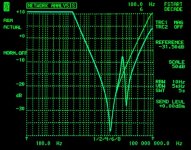
EDIT. See attached. The C values are 3.3uF and 150nF. Are those correct (sanity check)? Then what are the L's? (Hint: the L slope of the 3.3uF is already plotted. Vertical scale is dBOhms.
Attachments
Last edited:
Yes.is 0db ohms = 1r0?
and is -20dB ohms = 0r1?
Looks like I need more help.
from post17
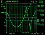
The two dips have impedance of 12.6milli-ohms @ ~1MHz and 39.8milli-ohms @ 6MHz
The impedance peak is 0.422 ohms @ 4MHz.
Putting 3u3F & 1MHz into L=1/C/(2PiF)² gives L= 7.68uH
What is that telling me?
Does it say that I have the calculations all wrong, or that the 3u3F capacitor has esr=~13milli-ohms and esl=~8uH
from post17
The two dips have impedance of 12.6milli-ohms @ ~1MHz and 39.8milli-ohms @ 6MHz
The impedance peak is 0.422 ohms @ 4MHz.
Putting 3u3F & 1MHz into L=1/C/(2PiF)² gives L= 7.68uH
What is that telling me?
Does it say that I have the calculations all wrong, or that the 3u3F capacitor has esr=~13milli-ohms and esl=~8uH
- Status
- This old topic is closed. If you want to reopen this topic, contact a moderator using the "Report Post" button.
- Home
- Amplifiers
- Power Supplies
- paralleling 10uf polyster to the psu bank increases sound quality? any benefits?