I too went live 5 minutes ago. I have now 9.9k in input and in absence of my RIAA resistors 18k in "External RIAA" connector. Everything looks as expected, input offset can be reduced to basically zero and is wandering a bit, however it remains neglectable low - no problem at all. Output offset is wandering faster but its never more than 30mV. Since I just powered up the first time that was to be expected.
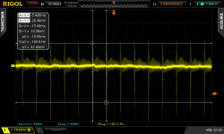
However, the scope shows this on output channel 1:
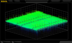
And this on channel 2:
Rails taken between regulator and amplifier (where bridged) all look similar to this:
Regards
Sven
However, the scope shows this on output channel 1:
An externally hosted image should be here but it was not working when we last tested it.
And this on channel 2:
An externally hosted image should be here but it was not working when we last tested it.
Rails taken between regulator and amplifier (where bridged) all look similar to this:
An externally hosted image should be here but it was not working when we last tested it.
Regards
Sven
Last edited:
When set at 1X, probes that come with 100MHZ budget scopes should not be better than -3dB 6MHZ to 10MHZ tops. So I wonder if you just pick up some FM radio band interference in the measurement loop. Is there a digital filter menu with low pass beyond the 20MHZ bandwidth limit standard option? If yes try limiting MHZ by MHZ to see if the picture clears.
pdul: High-pass filter - Wikipedia, the free encyclopedia
cutoff frequency =

Salas - to be honest I don't know. Have it only for a couple of weeks. Will check.
cutoff frequency =
Salas - to be honest I don't know. Have it only for a couple of weeks. Will check.
Salas - to be honest I don't know. Have it only for a couple of weeks. Will check.
Just gave it a try at X1 probes also and the only thing I could reliably capture from the circuit itself sans its dedicated regs was the 100Hz rectification residual breaking thru from the lab supply. Its the spikes in the graph.
Attachments
I believe 0.5uF would do it as it would cut freq below 3Hz.I wonder if one of you math professors can help me out with the value of a seriescap for the output of the paradise, if it will be loaded with 100ko, and which kind of cap that is best for the purpose?")
The best are teflon caps
Is it correct that the cutoff will be 1,59hz with 1uf, or am i completely of with my calc.?
Correct
Is it correct that the cutoff will be 1,59hz with 1uf, or am i completely of with my calc.?
Cut-off frequency
fc = 1.59154943092[Hz]
Btw, the same ~90MHz are visibe on the input with a much lower amplitude of ~1mV
40mV near 100mHz almost a nice sinus, is a bit of an problem for the 100Mhz scope, and probably does not tell a lot about the original signal. I think that Salas is right, some strong signal induced by the environment. If (and only when) the RIAA has a proper box, you may be able to stop this signal by adding some ferrite beads in the input (and probably output and signal ground) wires.
If it is still a problem then (when boxed
)
Last edited:
Cut-off frequency
fc = 1.59154943092[Hz]
Are you sure about that '2' (at the end)?
Are you sure about that '2' (at the end)?
Blame the RC calc. I declare myself "not guilty".
- Home
- Source & Line
- Analogue Source
- Paradise Builders