Tanks Frans.
One more thing to watch out for is cheapo cables on budget TT Like my Project RPM 4
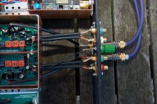
The cheap and nasty phono plugs have no insulation so they are connected to ground with the metal of the cheap and nasty piece of metal so there is a potential loop there.
Best thing one can do is to replace the wires straight from cartridge tags to the phono plugs.
I use 4 wires in pairs (L and R) in their own silicon sleeve and 2 Layers of cooper braid over the top of those
The cooper braid is connected on TT end with the ground cable from the arm and on other end has a lug for the connection to the Phono star ground
One more thing to watch out for is cheapo cables on budget TT Like my Project RPM 4
The cheap and nasty phono plugs have no insulation so they are connected to ground with the metal of the cheap and nasty piece of metal so there is a potential loop there.
Best thing one can do is to replace the wires straight from cartridge tags to the phono plugs.
I use 4 wires in pairs (L and R) in their own silicon sleeve and 2 Layers of cooper braid over the top of those
The cooper braid is connected on TT end with the ground cable from the arm and on other end has a lug for the connection to the Phono star ground
Last edited:
Did you rewire your tonearm ?I use 4 wires in pairs (L and R) in their own silicon sleeve and 2 Layers of cooper braid over the top of those
The cooper braid is connected on TT end with the ground cable from the arm and on other end has a lug for the connection to the Phono star ground
Yes I did a couple of years (maybe 4 or 5 ) back as I went Balanced INA with LT 1028
I am using single strand pure silver cores X 4.
Silver Insulated Wire Global Online Supplies - Product Line AG5494
This I have found is realy durable and light. Custom cables can be to heavy for same arms.
No broken wires at all while in use and abuse apart from solder joints.
Meybe I shuld have used the next size up
Last edited:
Maybe the gnd on the rca sockets is touching the casework.
This is an interesting point, the RCA connectors in and out should be mounted (any way that is what I prefer) on a Plexiglas insert (inserted into the back panel) to be sure that no (not any) signal or signal ground wire touches the chassis at that point!
Maybe this remark should be added to the builders guide
")
You just can see the insert (just) on this picture Balanced RIAA preamp | Flickr - Photo Sharing! it is on the outside
Attachments
Last edited:
Thanks guys for the interesting discussions re grounding rules. Thanks Franz for the ground scheme- now i understand it a bit more. I find that if i used screen IC the noise level is higher? May be the screen created a ground loop?.
quan
Easy sorted just cut the screen wire from the Paradise board before it reaches the phono plug
If those are grounded on the enclosure you won't need the binding wire to TT
Snip away one at the time and listen for results
Easy to resolder them in place later.
Me think Neutric phono plugs came with 2 plastic washers, fiber washers EG one find in Plumbing water taps kits are even better just drill oversize holes...
...
Maybe this remark should be added to the builders guide
...
Another possibility:
May I suggest that somebody of the design/construction team opens a wiki page for the Paradise?
Main Page - diyAudio
The wiki pages here are somewhat neglected here, but I consider this format as very useful tool for summarizing information.
On that page, links to the most important posts could listed.
This is an interesting point, the RCA connectors in and out should be mounted (any way that is what I prefer) on a Plexiglas insert (inserted into the back panel) to be sure that no (not any) signal or signal ground wire touches the chassis at that point!
Maybe this remark should be added to the builders guide
You just can see the insert (just) on this picture Balanced RIAA preamp | Flickr - Photo Sharing! it is on the outside
Thank you Franz. How do you implement input resistor loading switches? Can you show me a close-up image?.
quan
Thank you Franz. How do you implement input resistor loading switches? Can you show me a close-up image?.
quan
No loading-resistors implemented there (in the picture
), it is a MM RIAA that I did build. As strange as it may be, I did not build the Paradise RIAA (sorry ) (but I always be here and help with the PSU).P.s. The name is Frans
Not to be confused with the german style Franz !P.s. The name is Frans
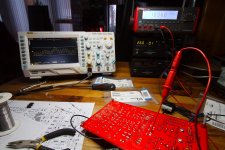
Here a picture that tells a 1000 words (I hope). The scope is at 10nS and 500uV, the HF is sampling artifacts. If you remove the sampling artifacts from the signal, then around 600 to 800 uV signal is there. With this I am happy, the PSU is unloaded, there is no shielding, sitting on the living room table near to the SMPS. This all is at the limit for the scope.
Someone will be happy to see this/his positive supply fixed, I will now continue with the negative supply.
Any remarks, let me know, I will be happy to discuss this.
Someone will be happy to see this/his positive supply fixed, I will now continue with the negative supply.
Any remarks, let me know, I will be happy to discuss this.
Attachments
Any remarks, let me know, I will be happy to discuss this.
Hi Frans,
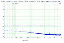
can you try something like this? You may easily read the PSU noise and ripple from my measurement.
Regards,
Pavel
Attachments
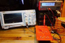
The funny thing is, I am still not sure why this one was oscillating (more than 2Volts pp), or in other words, why most others are not oscillating.
The things I did are:
1) Remove 2 MJE15031G from the positive supply and replaced by D45H11's. This lowered the oscillations somewhat but not much.
2) Paralleled the 330 ohm be resistors with 56 ohm resistors. Again, this lowered the oscillation somewhat (slightly more than in removing the MJE25031G's).
3) Added ce capacitors (as in the builders guide) but I had to use 4n7's and 2n2's to stop all oscillations.
There you have it, my report from the trenches.
Last edited:
Hi Frans,
can you try something like this? You may easily read the PSU noise and ripple from my measurement.
Regards,
Pavel
No (I'm sorry to say
) I cannot (I tried). The 10nS and 500uV is near the limit of the scope, there is absolutely no resolution in the FFT (it’s near empty ).Hi Frans,
can you try something like this? You may easily read the PSU noise and ripple from my measurement.
Regards,
Pavel
In your graph it is -105dB and with that I will be happy (unshielded and sitting near the SMPS).
- Home
- Source & Line
- Analogue Source
- Paradise Builders