I have forgotten to ask: what is a Paradise natural input capacitance?
Hands up who thinks its 10k.
Hands up who thinks its closer to 1.2k
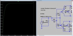
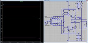
Here is a plot of the input current against frequency at 500uV input.
From this you can calculate the input resistance.
But now input capacitance? ... mmm how to do that") the problem is, it seems that the input impedance goes up at the high frequency range, making it an input inductance. Also the impedance slopes down (a bit) at the low frequency end of the graph, making the input capacitance seem very, very... small.
the problem is, it seems that the input impedance goes up at the high frequency range, making it an input inductance. Also the impedance slopes down (a bit) at the low frequency end of the graph, making the input capacitance seem very, very... small.
Obviously I do not have a clear cut answer.
From this you can calculate the input resistance.
But now input capacitance? ... mmm how to do that
the problem is, it seems that the input impedance goes up at the high frequency range, making it an input inductance. Also the impedance slopes down (a bit) at the low frequency end of the graph, making the input capacitance seem very, very... small.Obviously I do not have a clear cut answer.
Attachments
Last edited:
Measure/Simulate the bandwidth at a point before the RIAA filter with two largely different voltage source impedances. Any difference to narrower bandwidth should be due to input capacitance that you can reverse calculate. Measurement should be more reliable than simulation because the real total input capacitance includes connector and layout contributions beyond possibly doubting the transistor models for detail.
Here is a plot of the input current against frequency at 500uV input.
From this you can calculate the input resistance.
But now input capacitance? ... mmm how to do that
Obviously I do not have a clear cut answer.
Obviously input resistance depends on used load resistor but native impedance (no load resistor ) would be around 10k ( depending on the 100k pot setting) am I right ?
Could someone clarify Paradise gain , is it ~62dB?
Another question , MIIB RIAA is rigged towards more "exiting" kind of sound which one would give more flat response R.Cruz or Salas@
Stupid me
I did overlook the load resistor, now I have to do it all over, good catch!Here is a plot of the input current against frequency at 500uV input.
From this you can calculate the input resistance.
But now input capacitance? ... mmm how to do that
Obviously I do not have a clear cut answer.
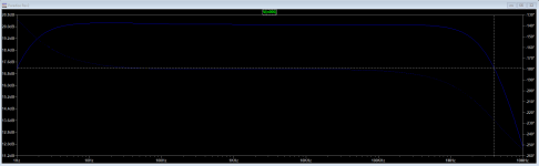
Again, but now removed the loading resistor, looks like 2.8k input impedance.
P.s. Seems to indicate [capacitive] loading at frequencies higher as 100kHz, probably due to the input capacity.
Attachments
Last edited:
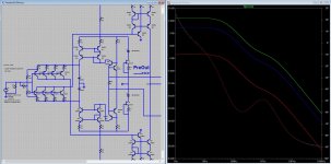
This is (again) inconclusive (in simulation) the source impedance is stepped 10, 1k and 10k the graphs at the input of the RIAA look (almost) equal.
Someone needs to measure
Again, now the loading resistor removed and stepped from 10R up to 100kR still inconclusive, still someone needs to measure
Attachments
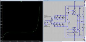
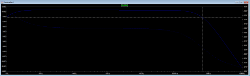
And finally, generator impedance 10R...100kR measured at RIAA but non lineair parts of the RIAA removed, so that any BW limit due to input capacity may be more clear.
Still inconclusive
P.s. I could simulate over 100kHz but I do not know the validity of that?
P.s. But (see next posts) one may come to some conclusion? again the validity of that?
Still inconclusive
P.s. I could simulate over 100kHz but I do not know the validity of that?
P.s. But (see next posts) one may come to some conclusion? again the validity of that?
Attachments
Last edited:
From the graph it seems to be over 100kHz(?), using 2.8kR and 100kHz the capacity would be less than 580pF (now please will someone measure!) And (as indicated by Salas) do not depend to much on this number (maybe the only thing to bet on this is your mother in law).
P.s. The input current plot from post #4087 seems to indicate the same.
And (as indicated by Salas) do not depend to much on this number (maybe the only thing to bet on this is your mother in law).P.s. The input current plot from post #4087 seems to indicate the same.
Last edited:
Probe at a non RIAA affected node. Try at the input stage's collectors.This is (again) inconclusive (in simulation) the source impedance is stepped 10, 1k and 10k the graphs at the input of the RIAA look (almost) equal.
Someone needs to measure
Probe at a non RIAA affected node. Try at the input stage's collectors.
Yes... I did
e.g. you where to fast Could someone clarify Paradise gain , is it ~62dB?
Another question , MIIB RIAA is rigged towards more "exiting" kind of sound which one would give more flat response R.Cruz or Salas@
It was measuring 62dB on mine (Rev2 PCB). My RIAA values twist was http://www.diyaudio.com/forums/analogue-source/218625-paradise-builders-199.html#post3438188
I had also used half the total mF at the emitters and deleted their bypasses. For earlier subsonic roll-off.
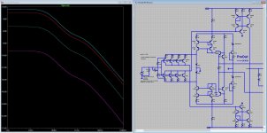
At the input stage's BC337 collectors. See, first attachment is for 50 Rs second is for 1000 Rs. RL=500.
Attachments
Would also indicate a Ft over 100kHz, giving simulation limits I would say inconclusive. And if an conclusion would be made, the Cin will be less than 600pF (as before).
Agree?
P.s. I think that 4Mhz is not realistic for the non-virtual (an actual build) version of the Paradise.
Someone needs to measure!
Agree?
P.s. 660kHz will be less than 100pF (not to be trusted).
Agree?
P.s. I think that 4Mhz is not realistic for the non-virtual (an actual build) version of the Paradise.
Someone needs to measure!
Agree?
P.s. 660kHz will be less than 100pF (not to be trusted
).
Last edited:
Alas, that <100pF indication can't be trusted as the real. Being transimpedance it makes things more complicated because Rs affects the gain changing the Miller.
p.s. Full circuit is flat 40kHz -3dB in sim when the RIAA filter is disconnected. But when probing at the input stage collectors it goes much wider.
p.s. Full circuit is flat 40kHz -3dB in sim when the RIAA filter is disconnected. But when probing at the input stage collectors it goes much wider.
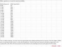
About an officially valid Spice file I would leave the choice to the guys who developed the circuit but for measurement (which is the best approach) I attach a most practical method for finding the input capacitance of tube phonos. Where there is a plate there is a collector so why not applicable here too. This table guide has been originally posted by kevinkr who is an expert contributor mainly in the forum's tubes section and an electronics engineer by profession.
Attachments
- Home
- Source & Line
- Analogue Source
- Paradise Builders