I have a problem, I have TP9 16,40V and in TP5 14,99V in the other board they are around 14,90 both of them. First board offset is wavering around 20mV but IC pin6 voltage is 14V. and slowly goes down while on the second board it is fixed at 0,626V. 327 andd 337 have been matched with the assembly guide circuit. Any idea?
TP9 should be -16.5V, TP5 should be +16.5V. Please check the voltage across R5, it should be just below 1.2V.
The voltage difference between TP9 / TP5 and the corresponding supply voltages, divided by 120Ohm will give you the current in each half of the circuit, and both are mirrored and summed up in the node "RIAA ext", at which point the result should be zero volts. However since two currents are summed up, and the impedance at this node is high, the "natural" voltage here cannot be expected to be zero, hence the servo is needed. But this voltage should be as close to zero as possible (and hence the two currents as well matching as possible), because the servo is designed with little "authority".....
If the IC output voltage is 14 V it means the servo is "in the corner" and has no ability to regulate any more. with the other board (IC output at 0.6V) the output offset should be zero- correct?
Please check if all transistor soldering points do not short-circuit to the ground plane, for starters.......
Thank you, I made an error putting the 120R in place of the the 220R. Now TP9 is -16,32 and TP9 is 16,34, in the other board -16,28 and 16,30. Input offset 0V, in R5 I have 1,19 and 1,18, in Ext RIAA I have up and down from 20 to 400mV in the other 15 to 200mV. Problem is output offset that is moving around 1V and IC pin6 17,02V and moving around 200mV and IC pin6 8,72V second board. Input load is 10K. Transistors matching was done with thecircuit in the manual.
I cecked and receked for short or solder but all seem correct. Maybe I do it once more as before I did that stupid resistors inversion.
The Calvin boards aren't fitted now.
I cecked and receked for short or solder but all seem correct. Maybe I do it once more as before I did that stupid resistors inversion.
The Calvin boards aren't fitted now.
Patriz, do you have a picture, top and bottom of boards.
I'd often seen boards built for Calvin's with the 1 meg resistor omitted, that skews the offset, but doesn't sound like your issue.
I'd leave your boards plugged in for 70 hours so that the elcaps can form, this is the largest source of dc offset apart from air moving over the input stage. Once they've have formed you'll be better able to investigate.
Grounding!!??
I have separate chassis for PSU and Riaa´s,and I connected the Riaa outputs ground throgh 10 ohms resistors to the chassies (maybe this is wrong?).
But should the PSU ground be connected to the (Psu chassie)via 2 x10 ohms
resistorn,I asume the 2 chassies should NOT be directly connected together?
I have separate chassis for PSU and Riaa´s,and I connected the Riaa outputs ground throgh 10 ohms resistors to the chassies (maybe this is wrong?).
But should the PSU ground be connected to the (Psu chassie)via 2 x10 ohms
resistorn,I asume the 2 chassies should NOT be directly connected together?
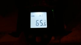
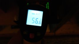
I measured some temperatures inside my closed box.
Air-temp inside is max 34°C after 3 hours.
Than I measured the heatsink closed box, which was 65°C on the hottest spot, on the semiconductors around 45-48°C.
Free air the temp of the heatsink is 56°C.
I measured all the other places in on the Paradise, hottest was 45°C, all capacitors not even reaching 40°C.
sq225917: can you tell me if I can use the c-rc snubber values?
Attachments
Grounding!!??
I have separate chassis for PSU and Riaa´s,and I connected the Riaa outputs ground throgh 10 ohms resistors to the chassies (maybe this is wrong?).
But should the PSU ground be connected to the (Psu chassie)via 2 x10 ohms
resistorn,I asume the 2 chassies should NOT be directly connected together?
May I suggest the following:
connect the 3 cables (plus / gnd / minus) coming from the PSU only to the PCB (where the power should be connected)
connect the shield / case / earth of the PSU to the phono chassis at the ground post (right between the two input jacks)
connect short twisted wires between the input jacks and the input connectors on the PCB
10 ohm resistors, rectifier bridges, resistor / capacitor networks etc that people use to connect the chassis of the PSU to the protective earth of the wall outlet should be used with a lot of care - I recommend to not put them but check first without them, if you don't have hum then there is no need to use them, and in many cases the hum will come from somewhere else anyway.....
(there is a reason why "protective earth" is called "protective"...)
That should give you a hum-free setup. Let us know if that worked!
I measured some temperatures inside my closed box.
Air-temp inside is max 34°C after 3 hours.
Than I measured the heatsink closed box, which was 65°C on the hottest spot, on the semiconductors around 45-48°C.
Free air the temp of the heatsink is 56°C.
I measured all the other places in on the Paradise, hottest was 45°C, all capacitors not even reaching 40°C.
sq225917: can you tell me if I can use the c-rc snubber values?
thanks for the data, very good. Good industrial grade components will not have any (lifetime) issue with this.
You may want to check if little ventilation holes right above the heatsink (and ideally on the sides of the heatsink) would be possible, that way the warm air can move up and out, to be "replenished" by colder air coming from the sides. This will however create airflow inside the box, so shielding the input transistors thermally (as sq suggested) may be required (and always a good idea anyway)
I disconnected the servo and from the input to Vriaa all voltage are normal except on the collector of Q18 on which I have -12,01V that is about the output offset. I changed it with a new one but nothing changed. Is it such high offset voltage compatible with transistor non perfect matching?
Audiomania, I never measured actual snubber values for the group buy psu with the BLOCK transformers. I use Talema 70065k in my builds and the optimum snubbing combo for that is 10n-15n/82r.
Without having one of the BLOCK transformers in hand to measure I can't really advise. I know the resistor value will be between 20-200r, but I don't know exactly where and it needs to be within a couple of % to work best.
Without having one of the BLOCK transformers in hand to measure I can't really advise. I know the resistor value will be between 20-200r, but I don't know exactly where and it needs to be within a couple of % to work best.
The diodes kick back into the transformers which makes them ring. It's not high amplitude but it's visible on a scope. I use the Quasimodo pcb and a scope to test for ringing before I complete the boards. The Quasimodo is basically a square wave generator at 50hz with space for an onboard C-RC filter. Simple, effective and inexpensive.
The physical noise you are hearing from your transformers is due to poor winding and potting quality. The C-RC filter will not change this, but it will snub any electrical ringing coming from the circuit.
Two different things.
The physical noise you are hearing from your transformers is due to poor winding and potting quality. The C-RC filter will not change this, but it will snub any electrical ringing coming from the circuit.
Two different things.
sq225917,
Thanx for the explanation.
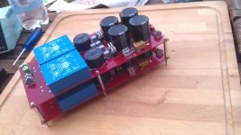
I've tried something :
I disconnected the Talema directly after the transformer, as you can see in the pic. I even desoldered the second xformer. Even than the xformer makes buzzing noises. Looks like I have to switch to the ones you use. Can I do with one xformer per side or shall I do the overkill like in mine? 😁
Thanx for the explanation.
I've tried something :
I disconnected the Talema directly after the transformer, as you can see in the pic. I even desoldered the second xformer. Even than the xformer makes buzzing noises. Looks like I have to switch to the ones you use. Can I do with one xformer per side or shall I do the overkill like in mine? 😁
Thank you, I made an error putting the 120R in place of the the 220R. Now TP9 is -16,32 and TP9 is 16,34, in the other board -16,28 and 16,30. Input offset 0V, in R5 I have 1,19 and 1,18, in Ext RIAA I have up and down from 20 to 400mV in the other 15 to 200mV. Problem is output offset that is moving around 1V and IC pin6 17,02V and moving around 200mV and IC pin6 8,72V second board. Input load is 10K. Transistors matching was done with thecircuit in the manual.
I cecked and receked for short or solder but all seem correct. Maybe I do it once more as before I did that stupid resistors inversion.
The Calvin boards aren't fitted now.
I solved the servo high output voltage from 17,02V to 0,5V reducing R38 from 120ohm to 118ohm. in one channel and from -8,72V to -0,8V reducing R14 from 120 to 119ohm!!!
Earthing, again...
I've bitten the bullet and bought three boxes for my Paradise phono amp. One box for the PSU and a box for each Paradise board. Which is all well and good, and will look much better than a tacky NAP 90.3 box for the amps and cobbled together PSU box.
Anyway, I've been trying to figure out the best earthing arrangement. I've looked at numerous Paradise boxings, re-read chunks of this thread and scratched my head over the earthing diagrams in the back of the assembly guide; this one...
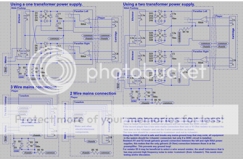
My current setup is earthed through the TT earth wire to mains earth (up through the TT's PSU). Interestingly this directly connected earth from the TT is connected to the GND of the Paradise boards. With the move over to a 774 Mission arm that earth will disappear. The TT's metalwork will still be earthed through the PSU and the arm's metalwork earthed up the left channel's screen, which is connected to cartridge's left GND in its phono plug.
So, I needed an earthing scheme that would work without a separate, earth connected tonearm wire.
This is what I came up with...

It looks safe, all the chassises are earthed...
With this layout the only connection between the mains earth and signal GND is via a DDCR in the Paradise boxes. No where else does single GND connect to main earth.
I have seen a few pictures were the GND from the 0V of the PSU board is directly connected to the chassis; that doesn't seem right to me.
I'd appreciate your thoughts.
- Home
- Source & Line
- Analogue Source
- Paradise Builders