I bought them over ebay from a chinese seller. The case is called 3207 or S-3207, but i took the ventilated top from BZ3207P case (which is the same size). The seller i bought from (sep_store168) did offer to drill the cut-out/hole in the front panel for the pot for free, when i emailed him before - don know if he always does that, or if it was because i ordered three cases at the same time.
If you want to shunt alot of current i would recommend to change to both ventilated top and bottom. Only top ventilation seems to works fine with approx 142mA/phase and 26V input at least.
I had them to only drill the front, whild i drilled the back myself - which was great because during building i got the idea to have two inputs on my phono stage.
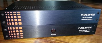
My Paradise build
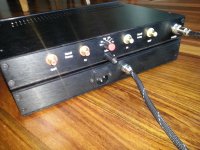
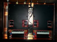
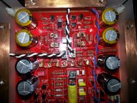
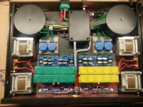
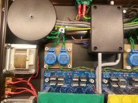
And here is my build of Paradise with Calvin buffer housed in two modushop enclosures. 40mm of height for this enclosures is a bit challenging but is as you can see is sufficient. For amp module I have thermo-coupled shunt heatsinks to the top plate od enclosure to improve cooling. Both amps are in separate copper enclosures painted black. For PSU I have custom made inductors of 1H mounted horizontally to fit into modushop enclosure and custom made toroids additionally enclosed in steel cans. In the plastic black box in the middle there is a junction point for 230V (for additional insulation of this dangerous voltage) and DDCR circuit.
As you can see I intended to have both enclosures sitting one on the top of another. Unfortunately I still have trace of hum in this configuration. This hum is gone as enclusures as side-by-side but this is not I want") . Initially I thought that this is related to toroids and therefore I used this steel cans – it helped but not fully. Another step forward was to re-arrange a bit grounding scheme for amps enclosure – better but still a bit hum.
. Initially I thought that this is related to toroids and therefore I used this steel cans – it helped but not fully. Another step forward was to re-arrange a bit grounding scheme for amps enclosure – better but still a bit hum.
As I can see from RollE2k’s post you used DDCR in the amp enclosure. I am curious if you have any trace of hum. What grounding scheme you used? I know that Frans posted picture of grounding scheme some time ago but this was specific for one enclosure. In the 2 enclosures there is a question where to have star ground point and how and where connect both enclosures together including DDCR location. Any suggestion appreciated.
Anyway – I believe that this is one of the most valuable DYI project you can build. If there is anyone still keeping your Paradise boards in captivity in your drawer – do yourself a favor and invest some time in this preamp. It is very worth if it. Thanks for all the team involved – hats off!!!
-jacek
And here is my build of Paradise with Calvin buffer housed in two modushop enclosures. 40mm of height for this enclosures is a bit challenging but is as you can see is sufficient. For amp module I have thermo-coupled shunt heatsinks to the top plate od enclosure to improve cooling. Both amps are in separate copper enclosures painted black. For PSU I have custom made inductors of 1H mounted horizontally to fit into modushop enclosure and custom made toroids additionally enclosed in steel cans. In the plastic black box in the middle there is a junction point for 230V (for additional insulation of this dangerous voltage) and DDCR circuit.
As you can see I intended to have both enclosures sitting one on the top of another. Unfortunately I still have trace of hum in this configuration. This hum is gone as enclusures as side-by-side but this is not I want
. Initially I thought that this is related to toroids and therefore I used this steel cans – it helped but not fully. Another step forward was to re-arrange a bit grounding scheme for amps enclosure – better but still a bit hum. As I can see from RollE2k’s post you used DDCR in the amp enclosure. I am curious if you have any trace of hum. What grounding scheme you used? I know that Frans posted picture of grounding scheme some time ago but this was specific for one enclosure. In the 2 enclosures there is a question where to have star ground point and how and where connect both enclosures together including DDCR location. Any suggestion appreciated.
Anyway – I believe that this is one of the most valuable DYI project you can build. If there is anyone still keeping your Paradise boards in captivity in your drawer – do yourself a favor and invest some time in this preamp. It is very worth if it. Thanks for all the team involved – hats off!!!
-jacek
Attachments
jacek:
I plugged in my tonearm, and also a cartridge just to check for hum for you. (and to finally check if there is any trouble for myself), all i can say that is i can hear little hum, when i have maxxed out the volume on my B1 preamp. Usually with this don't use volume more than maybe 12 a clock, and then its extremely high volume level. At this level i would pretty much instantly kill my speakers - so to sum it up, it's extremely silent.
I have don grounding like this. Pre-regulator in one case, the one from group buy. Grounded the chassis of pre-regulator straight to mains ground. Then i have 7pin plugs to other chassis. + gnd - from each channel, and chassis ground through the last pin. Inside the amplifier case i have the mains gnd from the pre-reg case to a star ground (which is the tonearm-ground post that also does have direct contact with the case), and another wire to the DDRC boards, and one wire from the other side of the DDRC to each amplifier board.
I did it like this, and not like Frans grounding scheme. This because at least i see the tonearm ground as an "extension" of the case.
I don't want to lift the chassis from mains gnd because of security reasons - but i would try it if i had alot of hum.
Hope this maybe can help you, and it looks like a nice and serious build you got there.
By the way jacek - how have you gotten the text on the back and front of your case?
Re: my grounding schema:
I have 'lifted ground’ concept. Power earthing (PE) goes from IEC socket in the PSU enclosure (through power filter) to DDCR. Other side of DDCR connects to PSU chasiss – to its ‘star connector’. I have connected here also shielding for PSU-Amp cable and shields made between primary and secondary winding of toroids. There is no any other connection to PSU circuit here. This PSU Star Connector connects to Amp star connector (through PSU-Amp cable). And here I have connections to Amp chasiss, both copper shields of Paradise PCB and GND od both channels of Paradise taken from input connector at PCB. All elements: Amp chassis, copper shields and GND of both channels circuts are isolated from each other and they connect only in this one point – Amp star GND. This point is also socket for tonearm grounding. Previously I have slightly different grounding scheme: GND from both paradise PCBs were connected together at input impedance selector and this point was connected to star GND through single wire. But I found that this arrangement was giving a bit more hum that I have currently. Sure – this is not that level of the hum to disturb normal level of volume. My concern is that when I max volume I can hear it – and simply I am looking for perfection here and I know that it can be achieved
Re: Lettering.
This is printed at UV Plotter. Sometimes advert agencies use this to print wall poster or big street posters. The only trouble is to find such one with high resolution – standard one do not have hi res. Other downside comparing to professionally made lettering is slightly less durability of it – you can potentially wipe off or destroy this lettering by use of sharp tool. But it is very easy, cheap and fast method, giving an option to have multicolor printing.
-jacek
This seems wrong.I have 'lifted ground’ concept. Power earthing (PE) goes from IEC socket in the PSU enclosure (through power filter) to DDCR. Other side of DDCR connects to PSU chasiss – to its ‘star connector’.
The Mains Input third wire the PE wire Must be permanently fixed to the Chassis.This is your Safety Earth. It is there for SAFETY ONLY.
It does NOT go to, nor through, any other component/equipment.
The Audio Grounding is completely different.
This has nothing to do with the safety of users and operators. They don't need to know anything about how you implemented the Safety Earth.
They just plug in interconnects, disconnecting and reconnecting, "knowing" that the Builder has incorporated all the Safety required.
The Audio Grounding is required for Audio operation.
The Audio Grounding does not need a chassis.
Look inside any portable and battery powered radio. There is no Chassis inside the plastic case.
All the Audio grounding will be and must be present for the radio to operate.
Last edited:
I finally fitted my Calvin buffers to the Paradise and powered up the right channel which I was able set the offset to zero.Things were left to warm up whilst I watched the last 18km's of the Vuelta and the offset with a slight adjustment I was able get down to +-1.6mv.
Unfortunately the left channel is sat at 151mv across the Calvin buffer with no adjustment possible.Where have I gone wrong with that board
Unfortunately the left channel is sat at 151mv across the Calvin buffer with no adjustment possible.Where have I gone wrong with that board

I removed the Calvin buffer this morning and checked for solder links;none found so refitted the board.No change unfortunately
On the good board I have +-18.2V at the buffer pcb with +-20mv from the in/ground connections.With the bad channel there is +18.2V and -16.8V with +-216mv at the in/ground connectios.
Have I damaged other components with soldering the BD140 in back to front originally.TIA.
On the good board I have +-18.2V at the buffer pcb with +-20mv from the in/ground connections.With the bad channel there is +18.2V and -16.8V with +-216mv at the in/ground connectios.
Have I damaged other components with soldering the BD140 in back to front originally.TIA.
Hi,
I think that problem occured here before.
The solution was to decrease R43a and b in value.
Due to the very high value of 150k the dc-regulating action is rather soft and sensitive, which means that small corrective actions across R5 require a large swing of the OPAmps output.
Take a measurement of Pin6 of the OPAmp.
Ideally that voltage should be close to 0V.
If its close to +18V or -18V reduce R43a and b.
Start with 47k.
BTW. even with a functioning Paradise You may want to control the OPAmps output voltage.
If it is considerably offset from 0V (>>+-5V) You may reduce R43a and b also.
jauu
Calvin
Last edited:
My kits arrived today (thanks Ulrich!), and I have already got started by building the pre-regulator boards. I noticed that mine came with 10R resistors for the CRC stage. The schematics on the group buy thread specify 47R or 30R I think. Is it worth replacing these with a slightly larger value?
Cheers,
Ed
Cheers,
Ed
My kits arrived today (thanks Ulrich!), and I have already got started by building the pre-regulator boards. I noticed that mine came with 10R resistors for the CRC stage. The schematics on the group buy thread specify 47R or 30R I think. Is it worth replacing these with a slightly larger value?
Cheers,
Ed
Hi Ed
10 Ohm is right for required 26 VDC output when the prereg is linked to paradise.
Take care
Werner
Hi Ed
10 Ohm is right for required 26 VDC output when the prereg is linked to paradise.
Take care
Werner
Excellent, thanks for clarifying that
It works
Turns out that the combination of a light bulb tester and not having changed the 10R resistors to 8R2's was not allowing things to power up properly.I fitted the 8R2 resistors and can know set things to zero across the Calvin buffer and have output offset in the region of 1-2 mv with an occasional spike to 5mv.I've just had a short listen and it sounds good.More serious listening over the next few days.
A big thanks to all concerned in the design of the Paradise
- Home
- Source & Line
- Analogue Source
- Paradise Builders