Berndt:
Regards
Sven
An externally hosted image should be here but it was not working when we last tested it.
Regards
Sven
I decided that I'm gone use the Nonmagnetic PRP resistors from Hificonnection and not the RN65, which are magnetic. My feeling is that on this level of audiosignal things like this do matter. Gonna use a Blackgate capacitor to for the 4700u in the circuit. The 6800u will be Panasonic FC, because Cerafine, Silmic and Blackgate dont have this big ones.
What C's do you all use for the RIAA?? I was thinking Silver Mica, or PIO, or are the Wima FKPs good enough? Has anybody any experience with Silver Mica??
I was searching the whole forum but only found something about the VCap CuTF as RIAA caps, but at the moment they are too expensive for me...
Any idea??
Hello,
anyone have a BOM of the components for the Paradise RIAA with suggested Mouser or Digikey reference codes?
Thanks a lot
Guglielmo
you have PM
Berndt:
Regards
Sven
many thanks, great way of explaining it, this will make its way into the assembly guide if you don`t mind!
I decided that I'm gone use the Nonmagnetic PRP resistors from Hificonnection and not the RN65, which are magnetic. My feeling is that on this level of audiosignal things like this do matter. Gonna use a Blackgate capacitor to for the 4700u in the circuit. The 6800u will be Panasonic FC, because Cerafine, Silmic and Blackgate dont have this big ones.
What C's do you all use for the RIAA?? I was thinking Silver Mica, or PIO, or are the Wima FKPs good enough? Has anybody any experience with Silver Mica??
I was searching the whole forum but only found something about the VCap CuTF as RIAA caps, but at the moment they are too expensive for me...
Any idea??
Hi, I used Wima FKP2 and also LCR caps in my builds, both were very good. Have CuTF but still could not find the time to put them..... There are a couple more recommendations but the name escapes me right now; will post tomorrow night
And, trying to un-confuse this a bit more, to be more clear. The 'impossible' means that it is impossible to have a 1mA current source (in this application) using the J109 and the 1mA was the design parameter for this current source.
On the other hand, the power supply will happily function using the J109 and 3k3, but; the supplied current will be between 600 and 750mA (not the design goal) and it will not be a CCS (not the design goal). Especially the last (it not being a CCS) hurts the performance of the PSU (but slightly).
FdW, I've ordered the 113 to sub the supplied 109. The Rgs is the gate resistor, I assume?
Just trying to get up to speed with the nomenclature. The 3k3 resistor that is currently used, will these all need to be replaced with a 1k as per you suggestion? Is there a corresponding series of numbers that goes with the 3k3 resistors that will end to be replaced with 1k resistors to accommodate the 113 device?
Thanks in advance for you time and attention.
What C's do you all use for the RIAA?? I was thinking Silver Mica, or PIO, or are the Wima FKPs good enough? Has anybody any experience with Silver Mica??
I used SM in several builds and it works wonderfully.... I did not like PIO in the riaa filter.
Finally I put them into boxes, Please excuse the rogue earth return wire om each channel I'm waiting for my 4-pin sockets and plugs to replace the 3-pin ones.
Now this first one is complete I shall start building up the R3 boards with my final component selection.
An externally hosted image should be here but it was not working when we last tested it.
An externally hosted image should be here but it was not working when we last tested it.
Now this first one is complete I shall start building up the R3 boards with my final component selection.
Hi to all!
Just received the pcbs from Alfred and trying to get everything else.
As i read this thread i found very valuable bits of information, but to tell the truth i got confused!
There is an oscillation or not? How this can be avoided?
What types of resistors/caps/etc. should i choose?
Any other changes/corrections that i should be aware of (e.g. on components or its values/currents/volts/ etc)? Could all of this be "sticky" e.g. on the top of the thread (just an idea...)?
I just want a safe operation and that is my way of choosing components.
Thank you all,
Kiriakos
Hi Kiriakos, just go with the components as indicated, and you should be fine. There is a small chance that the PSU might oscillate, but in version R31 this has been fixed. Please note there is a bug on the PCB, where one pad needs to be modified, I will repost the bug fix from Emil shortly.
For the RIAA section, no recommendations were given as most people tend to have their own ideas, but any good component will give you a decent start. My recommendation is Dale resistors and Wima FKP2 caps, but there is no limit really. For the rest, good metal film resistors and Panasonic caps for the 'lytics should be fine.
hope that helps....
Hi Kiriakos, here is the link that takes you to Emil's post: http://www.diyaudio.com/forums/analogue-source/218625-paradise-builders-223.html#post3498786
Hi to all!
Just received the pcbs from Alfred and trying to get everything else.
As i read this thread i found very valuable bits of information, but to tell the truth i got confused!
Me too, but the linkage posts FdW puts up help a lot. Post 2213.
http://www.diyaudio.com/forums/analogue-source/218625-paradise-builders-222.html
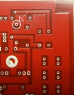
I didn't understand the board mod pic until I looked at my boards. If it looks like this you need to cut around the pad.
Attachments
Last edited:
Hi Kiriakos, here is the link that takes you to Emil's post: http://www.diyaudio.com/forums/analogue-source/218625-paradise-builders-223.html#post3498786
Hi Alfred,
i was thinking to use something like that (i have a spare):
Power Supply for Preamps
Thanks for clearing things up!
Hi Alfred,
i was thinking to use something like that (i have a spare):
Power Supply for Preamps
Thanks for clearing things up!
Hi, this will be overkill as the PCBs already contain a voltage regulator (much better than yours, IMHO). All you need is a transformer, rectifiers and caps, and some filtering, as described here:
http://www.diyaudio.com/forums/group-buys/222164-paradise-phono-preregulator.html#post3213898
hope that helps.....
Thanx Hesener and RCruz for your feedback so far.
As I read the site of Hificonnection better, I see there are no Black Gates anymore...so I will have to take some other Electrolytics....
I've read some in the internet about PIO and Teflon caps...would like to go for the PIO or Teflons, something like the Mundorf or so...but non of the tests was in a RIAA circuit.
Does someone else besides RCruz have some experience with the silver micas in the RIAA? What about Styroflex?
I think the Silver Micas will work well in the RIAA, and the Russian are cheap, so I can select the right ones.
Kiriakos: I think nonmagnetic resistors are a good way to go...
sq255917: very nice build!! WOW
Another Paradise is born!
Cheers everyone!
I finished the first stereo set using the last batch of boards. They worked right away from the first power up (after correcting the bug signalled by Emil) and the performance is outstanding. I have to congratulate the whole team for the project, and especially Alfred (hesener) for the PCB artwork and documentation, because his layout helped me to implement this build as I wanted. I also want to thank every builder that shared the details/issues and contributed to the Paradise builders and all related threads.
On top of the existing documented features, I had a few additional goals: to have the input transistors thermally coupled, to have them cooled, to have the mirror transistors coupled and to have them cooled. I managed to get my targets accomplished, although the cooling is just passive (as a side discussion, probably the next set will have the input stage cooled by Peltier elements). I strongly believe that one should aim for stable DC conditions, so that the output servo must have very little to work!
I will post later a few details of the build, but I beg for mercy") while evaluating my build, as I am not a skilled mechanical engineer, and nothing was planned and implemented meticulously. Also, to have this accomplished, I rotated all the transistors and mounted them down of the board. This is a very tough decision, as you are not allowed to make mistakes. Of course, everything is "undoable", but requires a lot of work to correct mistakes. For builders without patience, or people that are in a big hurry to finish, I suggest to use the well documented guide, and skip my approach. However, I guess it is worth to have a different approach and think before installing a component, as it spares lots of time and emotions in the debugging process.
while evaluating my build, as I am not a skilled mechanical engineer, and nothing was planned and implemented meticulously. Also, to have this accomplished, I rotated all the transistors and mounted them down of the board. This is a very tough decision, as you are not allowed to make mistakes. Of course, everything is "undoable", but requires a lot of work to correct mistakes. For builders without patience, or people that are in a big hurry to finish, I suggest to use the well documented guide, and skip my approach. However, I guess it is worth to have a different approach and think before installing a component, as it spares lots of time and emotions in the debugging process.
I have built an aluminium frame using L profile 15x15x2mm. I have drilled transistors holes using 4,5mm drill in a 40x4mm aluminium plate. That was a little tight and I have adjusted every hole with a round file; maybe 4,8mm holes would have been better. At least Diotec and Fairchild transistors used have an incomplete cilinder case with a diameter of 5 mm. Each transistor was forced inserted in the hole using a small desk vice. Having pieces of aluminium with 24 terminals each, it was not a nice task to fix them on hte PCB and the frame, but it is doable. I guess two days I spent only aligning these mechanical "small" details.
I have tested first the DC conditions. After few minutes they were stabilized very well. The offset at the input was 0.0V with the potentiometer set to the middle of range; using 100Ohm input load and 10Ohm input load made really no difference. In the test points, differences between positive and negative branches of a channel were in the milivolt range, and a big more for differences between channels in the same test points. Although I used input transistors with an hFE of 568 (measured with Atlas in the same day, same temperature, and under a blowing fan) I have no significant offset at the output. I measure around 0,2mV, fluctuating within +/- 3mV range. AC at the output, measured with a DSO having a 30MHz range was a clear line while the input had only the load resistance of 100Ohm. No oscillations and no problems at all (OK, I have a pocket scope, with only 50mV/div sensitivity, but anyway, able to detect a problem within 30MHz range).
After I left it running for one day, and being sure that everything is OK and safe to further testing, I have disconnected the preamp from the test room and brought it to the listening point. It took me some half an hour to make all the connections, after which I left a Status Quo record to play.
Terrible sound!!! With a cold shunt supply, for me it sounded like an old transistor portable radio. Imaging was really good, but the sound was crispy and lifeless. You can figure out how I felt, after so many weeks of work. Anyway, desperation is not something for me, and I listened further. For every minute passing by, the sound was improving a lot. After the first side of the disc it was comparable to the one from the integrated head amp in my Yamaha CX1000. Patiently, and avoiding any drop of alcohol - thus eliminating the subjectiveness from my judgement - I continued to listen, avoiding the first impression impact.
After around another hour, the sound was magnificent. Seismic bass and silky trebble, and a very good localization. I am not a good person to analyse an audio product, but the difference between startup and one hour running time is that HUGE! According to my quite good memory, this is the best phono preamplifier I have ever heard. The existing one in CX 1000 is also a good one. It uses two pairs of 2SB737/2SD786, but yeah... global feedback, input coupling cap (100uF electrolytic)... Paradise is clearly more silent and it's a big sounding difference between them, soundwise. I avoid to compare it to other preamps I listened in the past, as probably I cannot be objective.
As a source I use a Denon DP57 in the original state, equipped with Goldring Elite, 8Ohm DC resistance, and an excellent sound for the music I like to listen (mostly METAL, but also other genres guitar based).
Sorry for the long post; I just want to confirm what Joachim said: if you think every move in the build, it can/will run from the first power up. I will add later my construction details, with some pictures, as now I still need to listen. It's really addictive Cheers everyone!
Cheers everyone!
I finished the first stereo set using the last batch of boards. They worked right away from the first power up (after correcting the bug signalled by Emil) and the performance is outstanding. I have to congratulate the whole team for the project, and especially Alfred (hesener) for the PCB artwork and documentation, because his layout helped me to implement this build as I wanted. I also want to thank every builder that shared the details/issues and contributed to the Paradise builders and all related threads.
On top of the existing documented features, I had a few additional goals: to have the input transistors thermally coupled, to have them cooled, to have the mirror transistors coupled and to have them cooled. I managed to get my targets accomplished, although the cooling is just passive (as a side discussion, probably the next set will have the input stage cooled by Peltier elements). I strongly believe that one should aim for stable DC conditions, so that the output servo must have very little to work!
I will post later a few details of the build, but I beg for mercy
while evaluating my build, as I am not a skilled mechanical engineer, and nothing was planned and implemented meticulously. Also, to have this accomplished, I rotated all the transistors and mounted them down of the board. This is a very tough decision, as you are not allowed to make mistakes. Of course, everything is "undoable", but requires a lot of work to correct mistakes. For builders without patience, or people that are in a big hurry to finish, I suggest to use the well documented guide, and skip my approach. However, I guess it is worth to have a different approach and think before installing a component, as it spares lots of time and emotions in the debugging process.I have built an aluminium frame using L profile 15x15x2mm. I have drilled transistors holes using 4,5mm drill in a 40x4mm aluminium plate. That was a little tight and I have adjusted every hole with a round file; maybe 4,8mm holes would have been better. At least Diotec and Fairchild transistors used have an incomplete cilinder case with a diameter of 5 mm. Each transistor was forced inserted in the hole using a small desk vice. Having pieces of aluminium with 24 terminals each, it was not a nice task to fix them on hte PCB and the frame, but it is doable. I guess two days I spent only aligning these mechanical "small" details.
I have tested first the DC conditions. After few minutes they were stabilized very well. The offset at the input was 0.0V with the potentiometer set to the middle of range; using 100Ohm input load and 10Ohm input load made really no difference. In the test points, differences between positive and negative branches of a channel were in the milivolt range, and a big more for differences between channels in the same test points. Although I used input transistors with an hFE of 568 (measured with Atlas in the same day, same temperature, and under a blowing fan) I have no significant offset at the output. I measure around 0,2mV, fluctuating within +/- 3mV range. AC at the output, measured with a DSO having a 30MHz range was a clear line while the input had only the load resistance of 100Ohm. No oscillations and no problems at all (OK, I have a pocket scope, with only 50mV/div sensitivity, but anyway, able to detect a problem within 30MHz range).
After I left it running for one day, and being sure that everything is OK and safe to further testing, I have disconnected the preamp from the test room and brought it to the listening point. It took me some half an hour to make all the connections, after which I left a Status Quo record to play.
Terrible sound!!! With a cold shunt supply, for me it sounded like an old transistor portable radio. Imaging was really good, but the sound was crispy and lifeless. You can figure out how I felt, after so many weeks of work. Anyway, desperation is not something for me, and I listened further. For every minute passing by, the sound was improving a lot. After the first side of the disc it was comparable to the one from the integrated head amp in my Yamaha CX1000. Patiently, and avoiding any drop of alcohol - thus eliminating the subjectiveness from my judgement - I continued to listen, avoiding the first impression impact.
After around another hour, the sound was magnificent. Seismic bass and silky trebble, and a very good localization. I am not a good person to analyse an audio product, but the difference between startup and one hour running time is that HUGE! According to my quite good memory, this is the best phono preamplifier I have ever heard. The existing one in CX 1000 is also a good one. It uses two pairs of 2SB737/2SD786, but yeah... global feedback, input coupling cap (100uF electrolytic)... Paradise is clearly more silent and it's a big sounding difference between them, soundwise. I avoid to compare it to other preamps I listened in the past, as probably I cannot be objective.
As a source I use a Denon DP57 in the original state, equipped with Goldring Elite, 8Ohm DC resistance, and an excellent sound for the music I like to listen (mostly METAL, but also other genres guitar based).
Sorry for the long post; I just want to confirm what Joachim said: if you think every move in the build, it can/will run from the first power up. I will add later my construction details, with some pictures, as now I still need to listen. It's really addictive
Cheers everyone!- Home
- Source & Line
- Analogue Source
- Paradise Builders