I have been experimenting with bypass caps and accepted the analogue board is small so I have used remote locations and low impedance connections and yes bypassing the filter caps on the analogue do make a difference to the audio, interestingly more so on the +12V than the -12V. No idea why, perhaps the +12v feed to the opamps is more critical
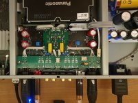
Anyway, I was wondering if leaving the wifi LAN antenna board connector disconnected would reduce any board noise if I never use it. assume there is no reason other than functionality to connect ?
Anyway, I was wondering if leaving the wifi LAN antenna board connector disconnected would reduce any board noise if I never use it. assume there is no reason other than functionality to connect ?
Yes, the decoupling caps it make a difference indeed. They it improve the noise level at the opamps power pins (said in a simple way).
As usual the wifi circuit is not working when not in use. This is by design. It may work the reception part of the module, as it should know when a wifi signal is available from outside, for eventual further communication. If cabled network is chosen in Menu, then the wifi section is disabled (not powered, not RF signals). You can just disconnect the connector of the wifi module from main board, but in this way, also Bluetooth section will not work.
As usual the wifi circuit is not working when not in use. This is by design. It may work the reception part of the module, as it should know when a wifi signal is available from outside, for eventual further communication. If cabled network is chosen in Menu, then the wifi section is disabled (not powered, not RF signals). You can just disconnect the connector of the wifi module from main board, but in this way, also Bluetooth section will not work.
I stumbled across this and realised that the two channel DAC did have a group of caps surrounding it on some variations, my unit has solder but no caps on this section highlighted in red in the review
Fortunately I don't use my separate two channel section and have no desire to strip completely again as I had had to make some solder joints with some larger caps to locate remotely
https://pcaudio-tistory-com.translate.goog/578?_x_tr_sl=auto&_x_tr_tl=en&_x_tr_hl=en&_x_tr_pto=wapp
Fortunately I don't use my separate two channel section and have no desire to strip completely again as I had had to make some solder joints with some larger caps to locate remotely
https://pcaudio-tistory-com.translate.goog/578?_x_tr_sl=auto&_x_tr_tl=en&_x_tr_hl=en&_x_tr_pto=wapp
Well, after enough long time since I finished the upgrade of my UB9000, I was able finally to finish the upgrade of the analogue audio board as well. Added mute relays for XLR/RCA outputs, and replaced the original circuits with my fully balanced post DAC module, based on OPA1622 opamps. Also OPA1622 chip for RCA final stage. It sounds really good indeed. Important gain in all sound parameters, comparing with the stock board.
Attachments
Yes, is right. The added analogue module is about stereo section (XLR/RCA). It is too complicate to do such modification for the 8 channels. Not enough place either. However, the relay mute module/board it fit for both MC and stereo sections (if fully populated).
Hi John,
The input voltage for these regulators it should be at least 2v higher than the regulated output voltage, and max 35v. So everything in the range of 15v - 35v input it should work fine in this case. Note that a too high input voltage, related to the regulated output, it result in increased heat dissipation. So an balance input-output voltages, function the current needed, it is recommended.
The input voltage for these regulators it should be at least 2v higher than the regulated output voltage, and max 35v. So everything in the range of 15v - 35v input it should work fine in this case. Note that a too high input voltage, related to the regulated output, it result in increased heat dissipation. So an balance input-output voltages, function the current needed, it is recommended.
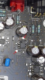
I have not measured it, but it should be around 100n. It is quite tricky unsoldering such type caps (for measurements purposes). It get damaged at once or at least it change their parameters/capacity. Yes, it are decoupling, placed on +/- power lines.
Here it fit well a quite large range of cap values (10n - 10µ). It is more about their physical dimensions. I think they did a very good choice in using SMD film decoupling caps there, as in general, an extended film caps use on audio board.
Here it fit well a quite large range of cap values (10n - 10µ). It is more about their physical dimensions. I think they did a very good choice in using SMD film decoupling caps there, as in general, an extended film caps use on audio board.
Thanks Coris.That caps are there... Please see the picture.")
Well, some considerations about film capacitors use. These components are of course better than ceramic ones and even electrolytic ones. The problem is that this type of caps become very big physically, when the capacity, and especially the voltage rating increase for such components. Their use in analogue audio sections it offer advantages when about noise level, absence of self resonances, and very low impedance associated, for the SMD film caps.
When using it in switching circuits, as original power board of UB820 (and of all the another consumer devices), it is important that for these caps as well, the impedance parameter being kept lowest as possible. If one may use such film caps with long legs to mount it on board, as replacement for another cap types, then the impedance component it become higher, and this it spoil the purpose of using it.
So, you could well use such film caps for values into 100nF or even 1µ, if the voltage rate it may not be that high (the higher voltages rating, the bigger physical dimensions). For decoupling function these film caps may be suitable in a switching power supply. In my opinion, it is no way to use this type caps instead of electrolytic ones.
However, one may keep in mind that in an switching circuit, the components are carefully adjusted for their optimal position, so to minimise the parasitic high frequencies generation. You will see on such SMPS boards, that some components are positioned in a quite weird position and sealed with compound to stay in that precise position. This adjustment is done while final testing of the board, to obtain the lowest noise level possible on the outputs, as lowest RF radiation in surrounding environment. Such SMPS circuits it are very sensitive to mutual coupling between components. When replacing one or another components, and especially caps and coils into a such SMPS board, there is very much danger to worsen dramatically their parameters, as the HF noise level on the DC outputs, as the RF radiation levels around that board. If an SMPS improvement is the target, then the quality of the DC outputs, the parasitic coupling in between the components, and the AC noise level on the DC outputs, it have to be carefully observed, and at least an oscilloscope is indispensable for this task. The amount of work is also quite high in such case. Without a carefully analyse of the results, after replacing components in this type of circuits, the final result is not at all an improvement, but a dramatically worsen of the SMPS parameters. On an analogue audio circuit, one may replace components and listen to the signal to appreciate the results. When it is about high frequencies (which is not possible to hear it), then good test instruments are necessary to appreciate the results (as professional skills as well).
If these last mentioned "parameters" are not present, then I strongly advice not to intervene on an SMPS circuit/board, as the final results it become most likely not an improvement...
Last edited:
Hi Coris
Have the power supply out now.Having to stick with the standard one.Found a few ics on the back of the board which complicates the circuit a bit.But if the SMPs shouln't be overloaded with capacitance as you say would it see the 4 caps total as 4300uf?(2 x 1000uf and 2 x 3300uf).If so would it be ok to change the first two 1000uf to 2200uf then change the second 3300uf to 2200uf so the SMPS sees 4400uf not 4300uf?
Thanks for any info.
Hi Smiffy,
Well, you can experiment a little bit to see if the SMPS it can sustain higher capacitances on its outputs and how much higher that capacitances may be. As usual, if a higher capacitance is placed on the HF rectified output of the SMPS transformer, the inrush current on start up it can simulate a short on that DC outputs, and then activate the protection of the SMPS and shut it down. In some cases a higher capacitance may be accepted, if the inrush curent on start up is under the protection level. That optimal capacitance (protection wise) it can be find experimentally. In case of this SMPS of UB9000 some filterting caps are placed after the serial regulators, which it regulate some of the SMPS outputs (for analogue section). Here the filtering caps capacitance it can be increased, as it is the serial regulator which it sustain the inrush current from the cap. You can try some scenarios in this respect, by replacing the original caps and testing the start up of the SMPS on bench first (outside the player). You should be carefully avoiding touching the high voltage area on the SMPS while it is powered on.
You will see that when you may place a too high capacitance on one or all of the SMPS outputs, the SMPS may shutdown after connecting it to AC power. Then you can chose a lover value cap so to have the SMPS up and running safely.
However, increasing the capacity of the filtering caps it may not improve the HF noise levels over the DC outputs... Also keep in mind that the filtering caps placed on an SMPS outputs it have to have a very low ESR (special type caps), and due to the high frequency of the SMPS AC outputs, the filtering caps capacity, placed after rectifier diodes, is not necessary to be very high for a very good filtering. The problem is (still be) that the HF noise it goes anyway through these filtering caps, and much sophisticated filtering is necessary to reduce such HF noise...
Last edited:
@Coris
Thx so you don't suggest follow via tutorial like this https://pcaudio.tistory.com/732
Thank you for your detailed answer.
Thx so you don't suggest follow via tutorial like this https://pcaudio.tistory.com/732
Thank you for your detailed answer.
Well, one can try one or another... For me who tried quite a lot in this field, it is all enough clear now, and my conclusions are expressed above. As far as no catastrophic outcomes occur, one can try, experiment... The best of all (but not the always the easiest one) it is replacing the SMPS with an linear type of PSU. For quite a low power needed (the case of most multimedia/streamer players), a linear PSU is the best power supply alternative, and it make indeed the big difference.
- Home
- Source & Line
- Digital Source
- Panasonic UB9000 - discussions, mods, improvements