Guys,
i know you both have your webpages excel workbook on Brian's , and freecad scripts on Lords
i want to tweak this design for different drivers
is the Staiper mini scooper MS-18 MK2 and MK3
source page here
MS-18 MKIII

i know you both have your webpages excel workbook on Brian's , and freecad scripts on Lords
i want to tweak this design for different drivers
is the Staiper mini scooper MS-18 MK2 and MK3
source page here
MS-18 MKIII
Your method of the Freecad templates. i have simmed some other templates you have and is a great tool !
i have thanked you already but another thank do not harm,
So thank You again !for sharing such a wonderful tool
for us people who can't translate a sub sketch in to HR DATA from scratch.
that being said i want to sim some drivers that i can acquire in the USA,
The author Staiper designed the MS18 for the Oberton 18" drivers and PD Drivers
in the USA is hard to get those.
from the original thread:
and btw, i am not sure about when this cabinet plan came to light but i think about 2010
so if you see , old plans use to love the use of the corner reflectors,
do we need to use the "new norm" that is get rid of those and also what diference makes to tweak the part shown
with the arrow

i have thanked you already but another thank do not harm,
So thank You again !for sharing such a wonderful tool
for us people who can't translate a sub sketch in to HR DATA from scratch.
that being said i want to sim some drivers that i can acquire in the USA,
The author Staiper designed the MS18 for the Oberton 18" drivers and PD Drivers
in the USA is hard to get those.
from the original thread:
Oberton 18NXB1600 sounded more harsh/rough and had a lot pressure.
The PD.1851 played more harmonic/melodic with more resolution but had less pressure.
and btw, i am not sure about when this cabinet plan came to light but i think about 2010
so if you see , old plans use to love the use of the corner reflectors,
do we need to use the "new norm" that is get rid of those and also what diference makes to tweak the part shown
with the arrow
Last edited:
Thank you.
You don't need to translate if the model translates for you. The major part of the data relies on calculating areas, lengths and volumes, those are not hard.
In a 2D drawing you can see only two dimensions as the name suggest per view, so to get 3D information you need more views, the is the reason you need front view, side view, top view, etc.
3D drawing are different.
Example: lets consider the Hornresp Offset drive (OD) model for this MS-18 case:
On top of the driver you can see the dimensions 250mm and the baffle thickness of 35mm. So the area (S1) on top of the drive (the dead end for OD driver model) is: (250-35)x(600-18) = 125130mm² converting to cm² as hornresp defines S1 = 1251,3cm²
The panel in the back of the driver and the baffle are parallel, so S2 = S1.
The distance between the dead end and the center of the driver is 260mm or 26cm (S2 in OD model is where you place the driver position)
Now you have all data for your first segment H1
S1 = 1251,3cm²
S2 = 1251,3cm²
L12 = 26cm
Assuming plywood thickness = 18mm
You will realize that quoted drawings for building are different them quoted drawings for simulation, and they are not direct translatable. So when you take any drawing and you want to tune it for a different driver it will be a hard work. In this sense FreeCAD model make your life easier, everything is already done for you, you can tweak just editing the quotes and you can add any quotes you want to compare with building drawings.
You don't need those reflectors if you are going to use the cab for low frequencies. Reflectors are necessary at higher frequencies when internal reflections can cause cancellations due to short wave length witch is not the case for frequencies below 200Hz probably.
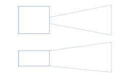
SuperScooper1
SuperScooper2
Above models can be used to simulate the MS-18 design. The decision for the model will depend from the freedom you want regarding "throat" size.
The Freecad model gives you the possibility to have two flared angles while this MS-18 looks like single flared.
Wasted space, don't replicate that.
for us people who can't translate a sub sketch in to HR DATA from scratch.
You don't need to translate if the model translates for you. The major part of the data relies on calculating areas, lengths and volumes, those are not hard.
In a 2D drawing you can see only two dimensions as the name suggest per view, so to get 3D information you need more views, the is the reason you need front view, side view, top view, etc.
3D drawing are different.
Example: lets consider the Hornresp Offset drive (OD) model for this MS-18 case:
On top of the driver you can see the dimensions 250mm and the baffle thickness of 35mm. So the area (S1) on top of the drive (the dead end for OD driver model) is: (250-35)x(600-18) = 125130mm² converting to cm² as hornresp defines S1 = 1251,3cm²
The panel in the back of the driver and the baffle are parallel, so S2 = S1.
The distance between the dead end and the center of the driver is 260mm or 26cm (S2 in OD model is where you place the driver position)
Now you have all data for your first segment H1
S1 = 1251,3cm²
S2 = 1251,3cm²
L12 = 26cm
Assuming plywood thickness = 18mm
You will realize that quoted drawings for building are different them quoted drawings for simulation, and they are not direct translatable. So when you take any drawing and you want to tune it for a different driver it will be a hard work. In this sense FreeCAD model make your life easier, everything is already done for you, you can tweak just editing the quotes and you can add any quotes you want to compare with building drawings.
so if you see , old plans use to love the use of the corner reflectors,
You don't need those reflectors if you are going to use the cab for low frequencies. Reflectors are necessary at higher frequencies when internal reflections can cause cancellations due to short wave length witch is not the case for frequencies below 200Hz probably.
SuperScooper1
SuperScooper2
Above models can be used to simulate the MS-18 design. The decision for the model will depend from the freedom you want regarding "throat" size.
The Freecad model gives you the possibility to have two flared angles while this MS-18 looks like single flared.
what diference makes to tweak the part shown
with the arrow
Wasted space, don't replicate that.
what are the difference between your 2 models... SS1 and SS2
looks like the same
OHH....


looks like the same
OHH....
you sim SS1 like a BR right ?
and SS2 like an OD ( offset driver )
what are the pros and cons of each model ?
Last edited:
You found the differences.
Probably the result are the same or very close considering the same box dimensions.
The model will depend what you are designing, copying or modifing.
If you are considering a chamber feeding into a horn, so the SS1 is preferable, you can control the throat size, the chamber size and so one, but you can't control the driver positions.
Considering SS2, there is no chamber, so the area behind the driver must be the same area of the horn throat.
You may need to simulate both to see what is better for your driver.
See the example below to get inspiration:
Attachments

Haaa, Master Jedi Sansui
I can see on the 1st model that there's a chamber and a constriction leading to the mouth, I have seen that in some bandpass designs that at the mouth there is a narrow opening.
I will play with both an see what outcome I can get with the sims.
Thanks for your input masta!!
(Insert Anakin Skywalker voice here)
- Home
- Loudspeakers
- Subwoofers
- Paging Brian Steele , LordSansui Staiper mini scoop MS-18 workbook